Finished geometry
Provide finished dimensions, tolerances, edge details and locating faces. Identify any grinding, coating or bonding allowance and include mating parts.


Hard ceramic permanent magnets
Define the part and the magnetic circuit together
Ferrite, also called ceramic magnet material, is used in motors, speakers and other permanent-magnet assemblies. The finished geometry, material grade, orientation and working conditions determine whether it suits your design.
Send your drawing, magnetic requirements and estimated quantity. Magnetstek reviews the proposed material, forming and finishing options, magnetization and inspection requirements before confirming the part-specific quotation.
Send your ferrite magnet drawingPrepare the RFQ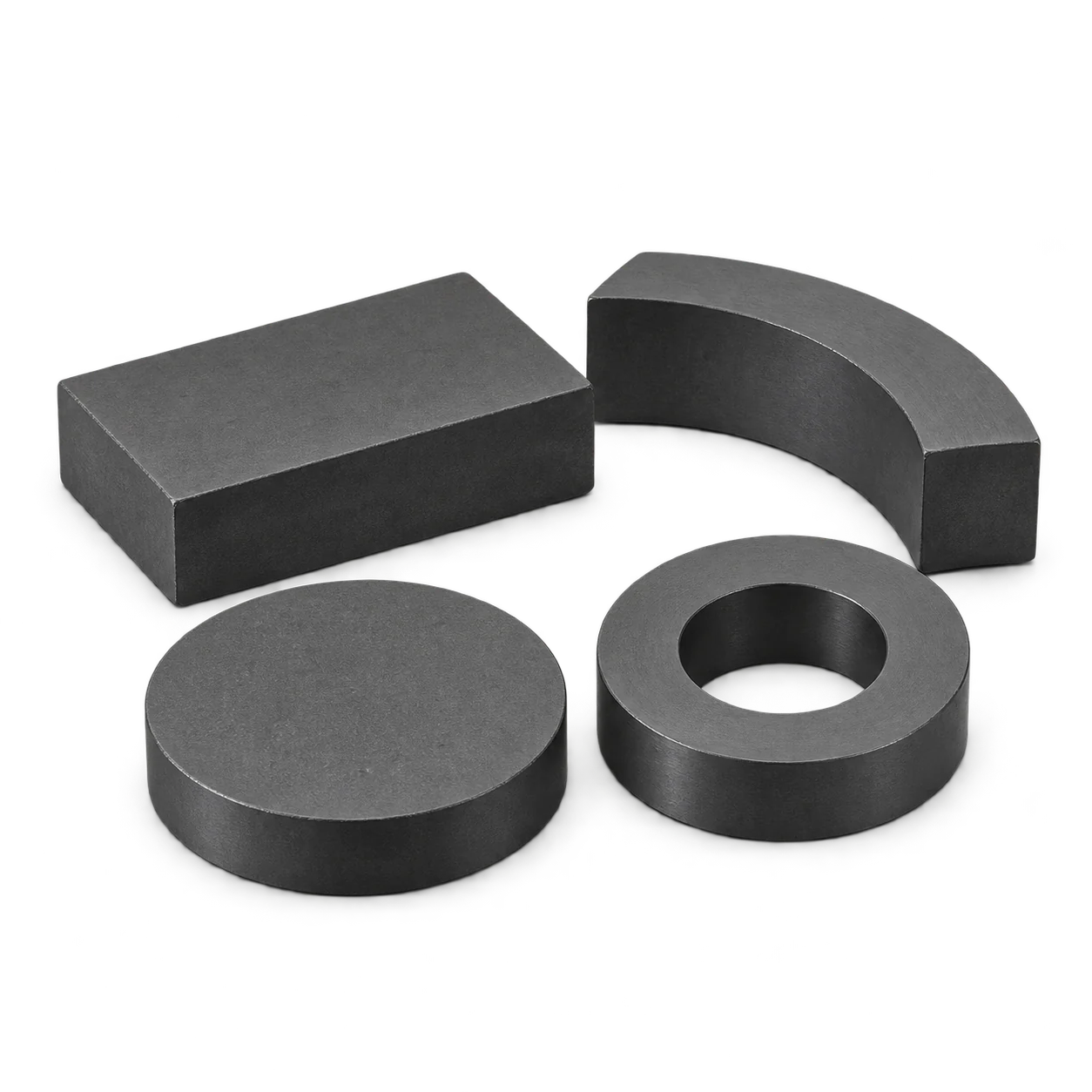
Show the mating parts, available space, working gap and load or field requirement. A material property and the output of the finished assembly are different checks; identify the evidence needed for each.
Prepare the specification
Separate confirmed requirements from choices that can be discussed during the drawing review.
Provide finished dimensions, tolerances, edge details and locating faces. Identify any grinding, coating or bonding allowance and include mating parts.
Give the requested grade and specification if fixed. Otherwise describe the magnetic function and ask for the proposed material data and relevant curves.
Mark pole faces, magnetization direction, pole pattern and any angular reference. Review compatibility with the material orientation and part geometry.
Define the field or force, measurement location, gap, fixture and allowed variation. Include the mating steel, magnet or sensor arrangement.
State low, continuous and peak temperatures, opposing fields, environment, vibration and how the brittle ceramic part is retained or bonded.
List sample and production quantities, drawing revision, visual and magnetic checks, required records, packaging and delivery destination.
Geometry concepts
Use these starting forms to describe your part. Tooling, grade, orientation, finishing and magnetization are reviewed for the particular drawing.
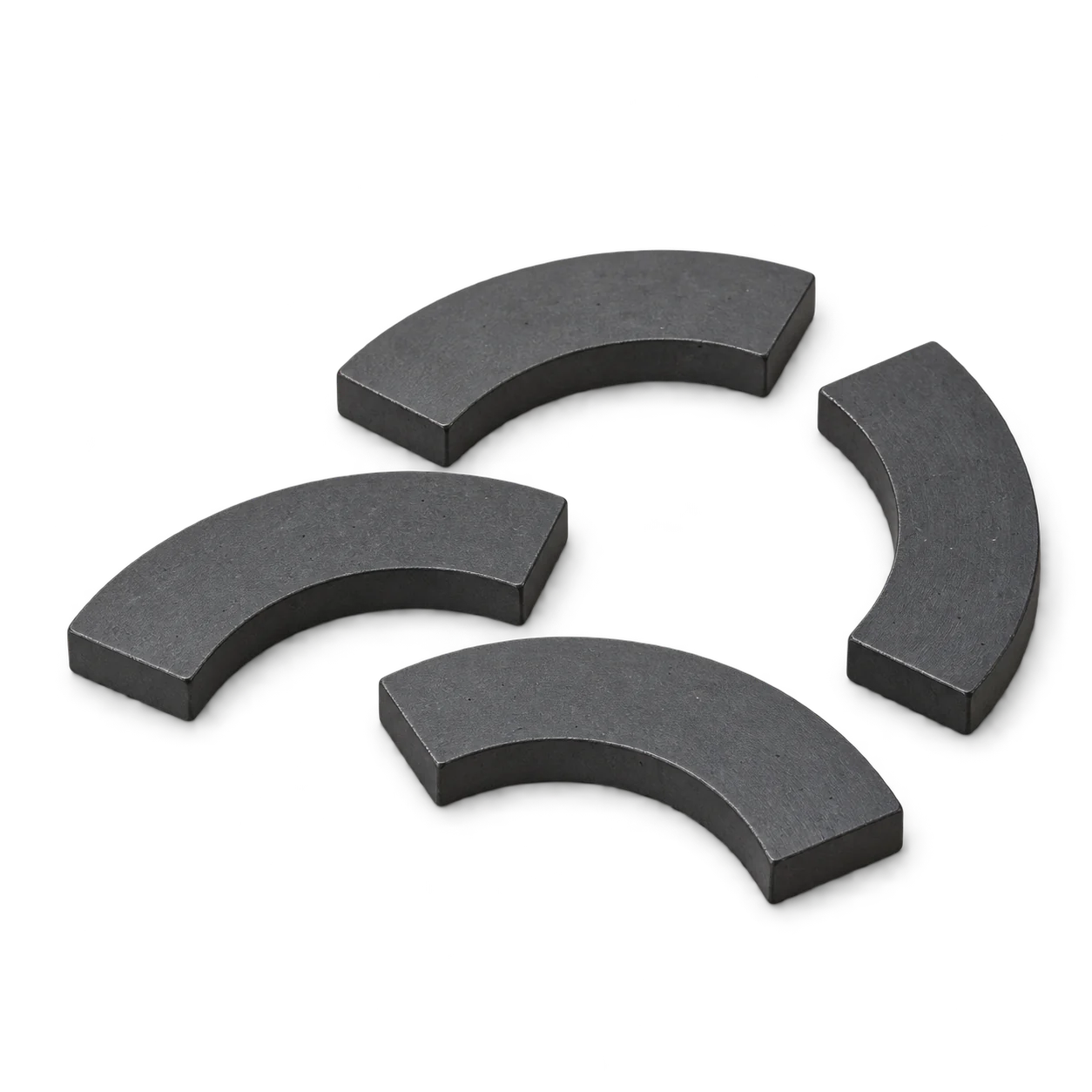
Specify inner and outer radii, arc angle, axial length and the required pole faces. Include the mating rotor or stator geometry.
Discuss this shape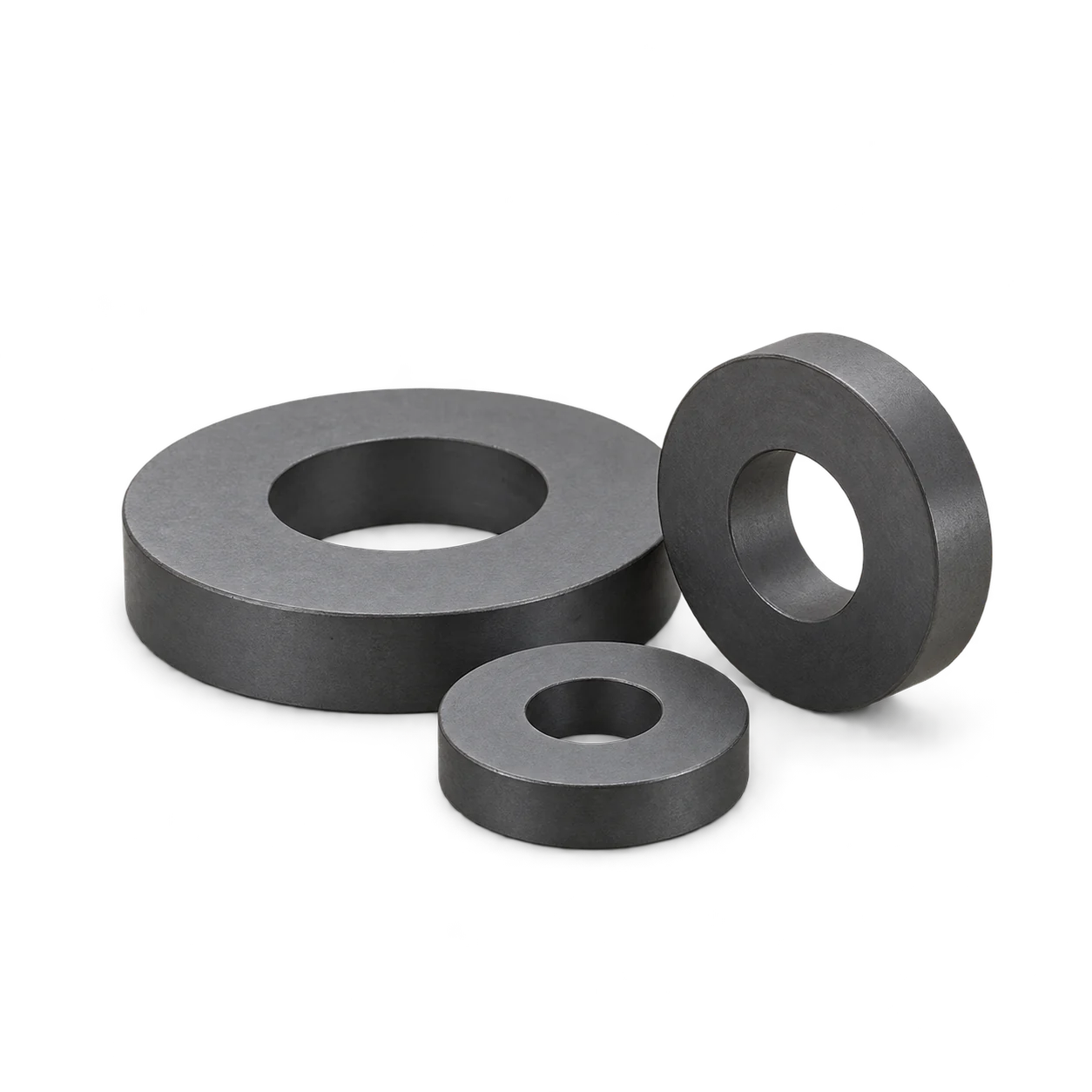
Show inner and outer diameters, finished thickness and the magnetization axis or pole pattern. A ring shape alone does not specify its poles.
Discuss this shape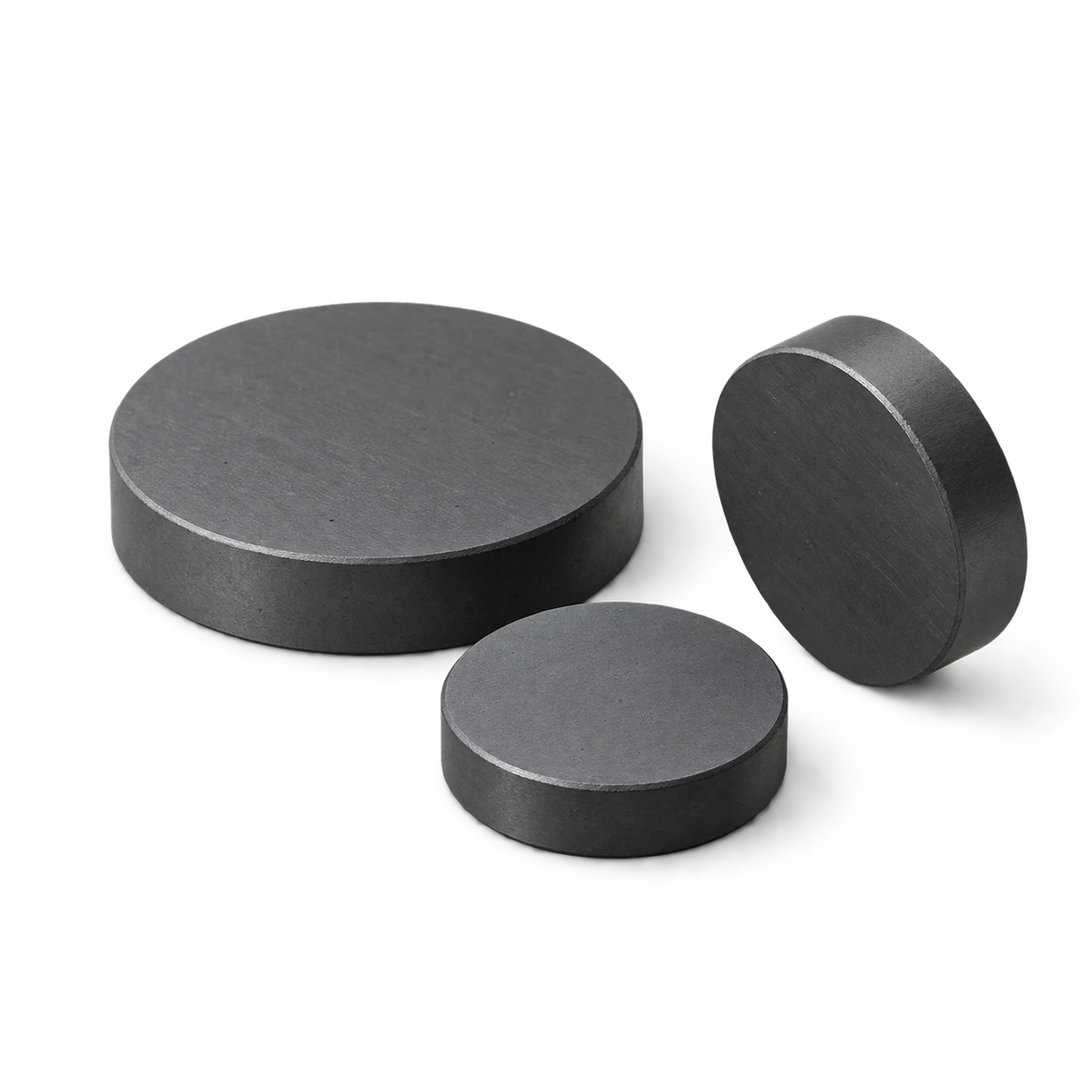
Give the finished diameter and thickness, active face and edge requirements. Include the working gap and retention or field test.
Discuss this shape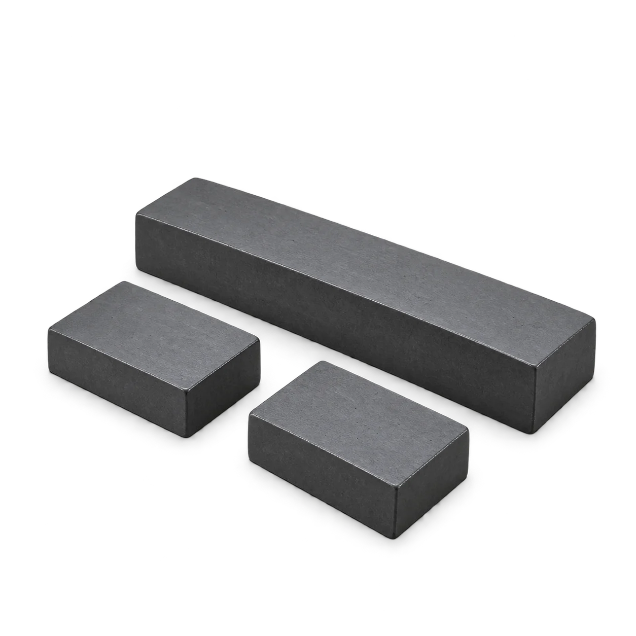
Define length, width, thickness, locating surfaces and the magnetization axis. Review thin sections and how the part is mounted.
Discuss this shapeAI-generated illustrations, not actual stock photographs. The pictured proportions do not establish available dimensions, tolerances or magnetic performance.
Send the complete drawing for feasibility review. A bread-shaped profile, sphere or other special outline needs its own forming, finishing and magnetization assessment.
Discuss a bread-shaped profileDiscuss a spherical designFor process-specific questions, review wet-pressed ferrite magnets alongside the drawing.
Application review
Provide the rotor or stator layout, air gap, pole arrangement, temperature range and relevant opposing fields. Check the proposed grade in that magnetic circuit.
Describe the magnet geometry, steel parts, working gap and required flux or field. Review the complete magnetic circuit and finished assembly checks.
Specify the mating material, gap, load direction or sensor position. Account for the holder, adhesive and mechanical retention when defining acceptance.
Use these application questions to prepare a review. Suitability and any product-specific qualification must be established for the finished part and assembly.
View the existing overview video. Confirm the proposed part and its technical records separately. Open the video on YouTube →
Technical reference
Connect material selection with the finished dimensions, magnetic circuit and acceptance method.
In this product context, ceramic magnet means hard ferrite permanent-magnet material, commonly based on strontium or barium ferrite. Soft ferrite used for transformer or inductor cores has a different magnetic function. The composition name alone does not establish the finished grade or application performance.
Anisotropic ferrite has a preferred material direction established during forming; isotropic material has no deliberately aligned preferred direction. The final pole arrangement must suit the material orientation and geometry. Mark the required pole faces and any multipole pattern on the drawing before confirming the proposed process.
Identify the proposed grade, producer or governing specification, revision and test conditions. Request the applicable Br, Hcb, Hcj and maximum energy product data, plus temperature-dependent demagnetization curves where needed. Confirm that the documents apply to the quoted material. Similar-looking grade codes are not enough to establish equivalence. A field or pull test alone does not identify the material grade.
Ferrite is a brittle ceramic and can chip or crack under impact or concentrated loads. Show critical finished dimensions, edge requirements and support or retention features. Review the assembly method, vibration and handling conditions with the drawing. Agree tolerances and visual acceptance for the proposed process rather than assuming that every outline or thin section is feasible.
Review the proposed grade at both the low and high operating temperatures, with the finished geometry, working point and opposing field. Ferrite can suffer irreversible low-temperature demagnetization under unsuitable conditions. Use the relevant material curves; neither a generic temperature range nor the Curie point establishes a safe operating limit.
Specify the required surface condition, cleanliness, bonding or particle-retention needs and service environment. If a finish or encapsulation is proposed, confirm the material, coverage, dimensional allowance and inspection method. Assess adhesion and assembly compatibility on samples. A coating is not a substitute for a mounting design that protects brittle edges.
Define the measurement location, working gap, temperature, fixture, orientation and allowed range. A gaussmeter reading and a pull-off test answer different questions. Use the intended mating parts and an agreed test method for acceptance; include polarity or pole-pattern checks where the assembly requires them.
Compare candidate grades in the available space and complete magnetic circuit. Review the required field or force, temperature range, opposing fields, environment, assembly method and total quoted construction. Confirm sample performance under the same conditions. A material name alone does not determine which option fits the application.
Describe vibration, shock, access by users, nearby sensitive components and possible fragment release. Review retention, clearances and handling precautions for the finished assembly. A material description does not establish toy, food-contact or medical suitability. State the product-specific tests and documents your application requires; confirm them before ordering.
Confirm the drawing revision, proposed material, orientation, magnetization, dimensional and magnetic tests, sample plan and required records. Include packaging and delivery-destination requirements. Specify whether a request concerns magnetized or unmagnetized parts. Availability, tooling, sample quantities, minimum order, price and delivery are confirmed in the individual quotation.
External material references explain technical principles and examples. Use the agreed data and inspection records for the actual material proposed in your quotation.
From requirement to quotation
Step 1
Send finished dimensions, mating parts, magnetic requirements, operating conditions and quantities.
Step 2
Discuss grade, orientation, forming and finishing options, magnetization and any tooling needs.
Step 3
Define dimensional, visual, polarity and magnetic-output checks and the documents requested for samples.
Step 4
Review the drawing revision, proposed construction, sample plan, packaging and commercial terms.
Documents and related options
Review process questions alongside the required geometry and material orientation.
Wet-pressed ferrite options →Prepare the finished dimensions, pole arrangement and operating conditions.
Prepare the drawing →Identify the visual, dimensional, polarity and output evidence needed.
Plan inspection →Read the stated scope of the existing material-sales certificate.
ISO 9001 scope details →Include any holders, backing steel and retained components when reviewing magnetic assemblies. If another material is being considered, compare the same requirements with NdFeB or SmCo magnet options. For research-system components, describe the system-specific requirements in the MRI/NMR component review.