Finished geometry
Include outer dimensions, thickness, hole positions, edge distances, datums and critical tolerances. State whether dimensions apply after coating.


Screw-mounted magnets · Drawing review
Match the hole, fastener and magnetic function
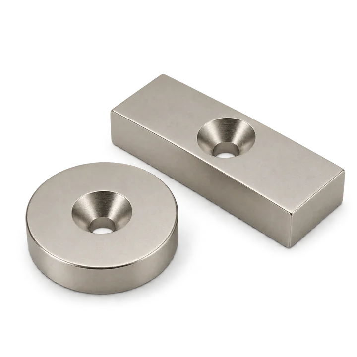
Countersunk magnets have a tapered recess around a mounting hole to accommodate a matching screw head. Magnetstek reviews NdFeB, SmCo and pot magnet requests against the finished geometry, fastening arrangement, required magnetic output and service environment.
Send the part drawing and screw specification with the mating surface, working gap, load direction and quantity. Feasibility, material, samples and commercial terms are confirmed for the particular quotation.
Send your drawingPrepare the RFQ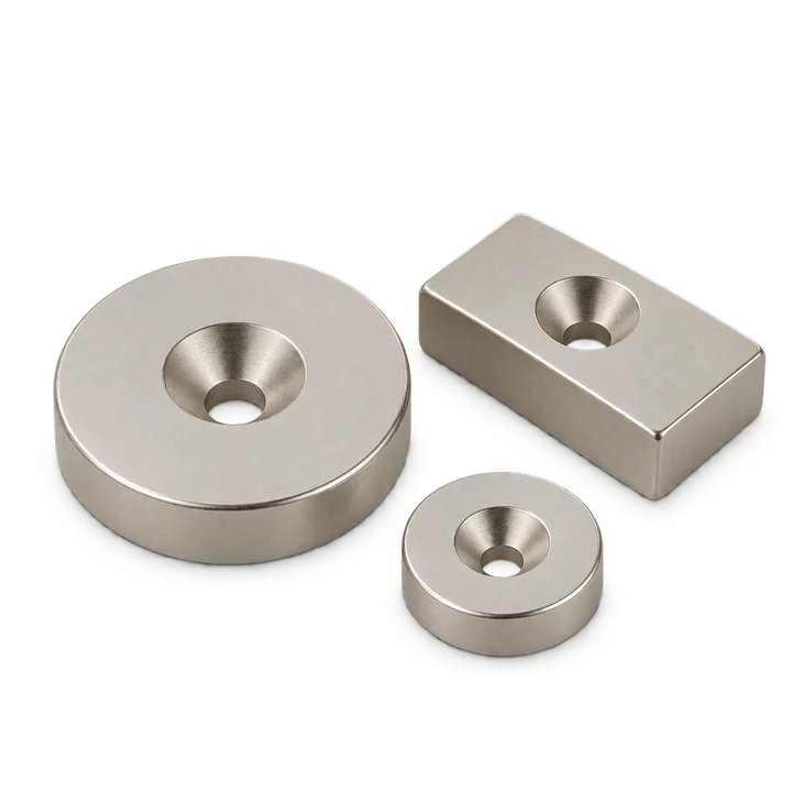
The screw head, hole profile and supporting surface must work together. Agree the finished part dimensions and assembly checks before selecting a magnet by shape alone.
Prepare the specification
Supply the magnet drawing and the matching fastener detail. Mark fixed requirements and any dimensions or material choices open for discussion.
Include outer dimensions, thickness, hole positions, edge distances, datums and critical tolerances. State whether dimensions apply after coating.
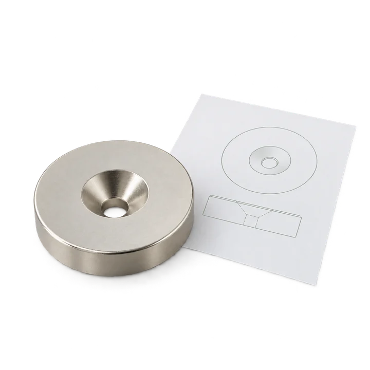
Define the through-hole diameter, recess profile, countersink diameter and angle, or counterbore diameter and depth. Include the fastener specification.
State the useful field or holding-force requirement, mating material, contact area, working gap, load direction and the proposed test conditions.
Mark the pole faces and magnetization direction relative to the countersunk face. For paired magnets, show which faces meet in the assembly.
Describe temperature, moisture, chemical exposure, coating, substrate and support under the part. Include retention and installation requirements.
Give sample and production quantities, dimensional and magnetic checks, coating requirements, records and any polarity identification or packaging needs.
Material & construction
Include the drawing and application conditions with the material choice. Confirm the proposed part and test method before ordering.
Review the grade, finish and operating conditions with the required field or holding force and the complete mounting detail.
Discuss this option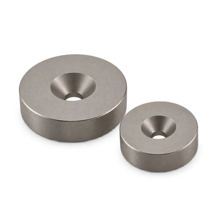
Confirm the grade, geometry and temperature requirements for the actual magnetic circuit. The hole and fastening arrangement need a part-specific review.
Discuss this option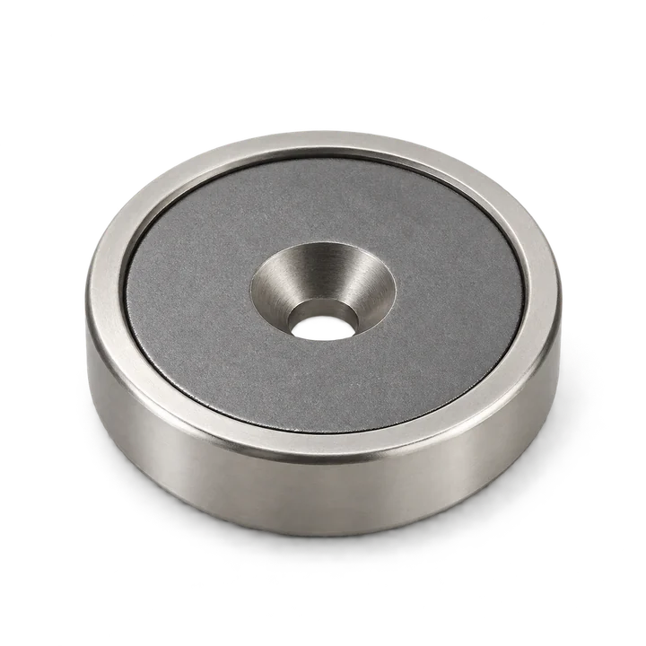
A steel cup is part of the magnetic and mechanical arrangement. Define the working face, cup envelope, fastener and actual mating surface.
Discuss this optionAI-generated illustrations, not to scale. Appearance does not identify a verified grade, stock part, holding force or manufacturing limit.
Hole terminology
A conical recess is used with a matching tapered screw head. Specify the opening diameter and included angle alongside the through-hole and finished thickness. Show the side of the part where the recess is required.
A cylindrical recess has a different profile. Specify its diameter and depth with the through-hole and fastener head details. The two names should not be treated as interchangeable on the drawing.
For recesses on both faces, show both profiles and the remaining section between them. Do not infer the angle, depth or suitable screw from a general product illustration.
Autodesk’s hole feature definitions distinguish conical countersinks and cylindrical counterbores.
Technical reference
Use these checks to connect hole geometry, fastening and magnetic acceptance.
Include the finished outline, thickness, hole center positions, through-hole and recess geometry. Mark the countersunk face, critical edge distances and dimensions after coating. Include the screw specification and a section view where the recess profile or remaining section is not clear.
A recess on one face establishes a specific fastener entry side. If recesses are required on both faces, dimension each profile and show how the part will be mounted. A second recess changes the remaining section and must be reviewed with the part thickness, material and fastener.
Match the screw head profile to the hole, and define the supporting surface and alignment. Sintered neodymium magnets are brittle; excessive tightening or impact can break them. Agree a controlled installation procedure for the actual fastener and substrate. Do not apply a generic torque value to an untested assembly.
Mark the required pole faces and magnetization direction relative to the recess and mechanical references. If two magnets meet, show the orientation of both parts and the contacting faces. Hole shape does not establish the pole arrangement. Include the polarity or output check used for acceptance.
Describe the actual mating material, thickness, contact area, coating, gap and direction of loading. State the fixture and test method with the required force and allowed variation. Normal pull-off, sliding and off-center loading are different test conditions; compare samples under the same specified arrangement.
Provide the proposed material or grade, operating temperature, peaks and exposure conditions. Include moisture, cleaning chemicals and the mounting substrate. Confirm the finish, coating allowance, working point and any adhesive or housing limits with the particular part; neither material family nor coating name alone establishes service life.
If the design includes a steel cup or holder, show its complete envelope, working face, mounting hole and mating surface. Evaluate the magnet and cup as an assembly rather than assuming a bare magnet and a pot design have the same output or load capacity. Identify the mechanical retention and inspection requirements.
Agree critical finished dimensions, recess profile, coating condition, pole orientation and magnetic output under defined conditions. List sample quantities, requested material data and inspection records. Minimum order, sampling and lead time are confirmed with the individual quotation.
From drawing to quotation
Step 1
Share the magnet geometry, hole profile, fastener detail and quantity.
Step 2
Discuss material, magnetization, finish, mating surface and mounting conditions.
Step 3
Confirm the drawing revision, sample checks, force or field test and required records.
Step 4
Review the proposed part, quantities, price and delivery before ordering.
Documents & related options
List required material data, coating information and inspection records in the inquiry. Confirm which documents apply to the quoted part and can be supplied.
Specify geometry, magnetic function and mounting interfaces.
RFQ guide →Agree the dimensional, pole and magnetic acceptance methods.
Inspection checklist →Review the steel interface, working gap and mechanical requirements.
Magnetic assemblies →Read the stated scope of the existing material-sales certificate.
ISO 9001 scope details →Installation context: K&J’s countersunk magnet discussion covers polarity, fastener use and breakage during tightening. Its product examples, torque tests and numerical results do not specify a Magnetstek part.