- Custom Magnets
- Standard Magnets
- Mounting Magnets
- Magnetic Assemblies
- About Us
- Knowledge


Menu

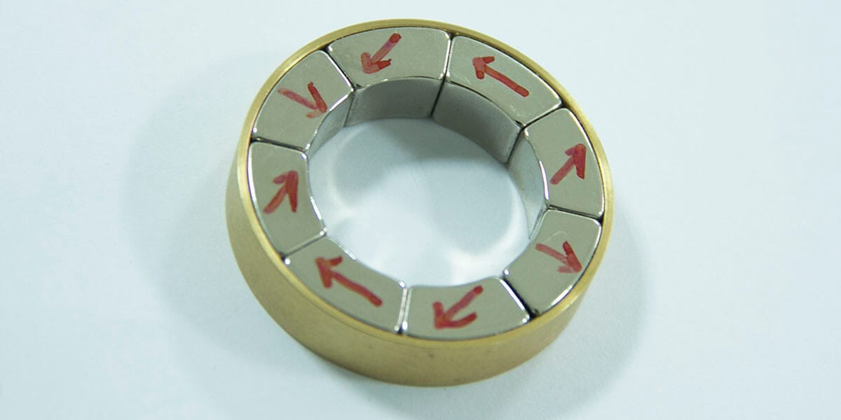
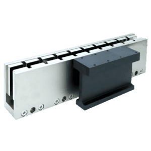
A Halbach array uses permanent magnets with different magnetization directions to concentrate the useful field on one side of a linear assembly or within a cylindrical assembly. The field at a working point and the stray field depend on the geometry, magnet grade, dimensions, and gap.
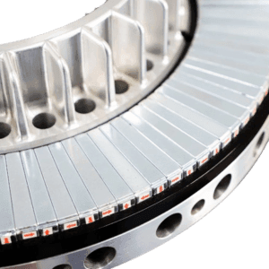
Magnetstek reviews circular, linear, and irregular Halbach assembly requests against the drawing and field requirements. Tell us where the field is needed, the operating temperature, available space, mounting constraints, and expected quantity so we can review the design before quoting.
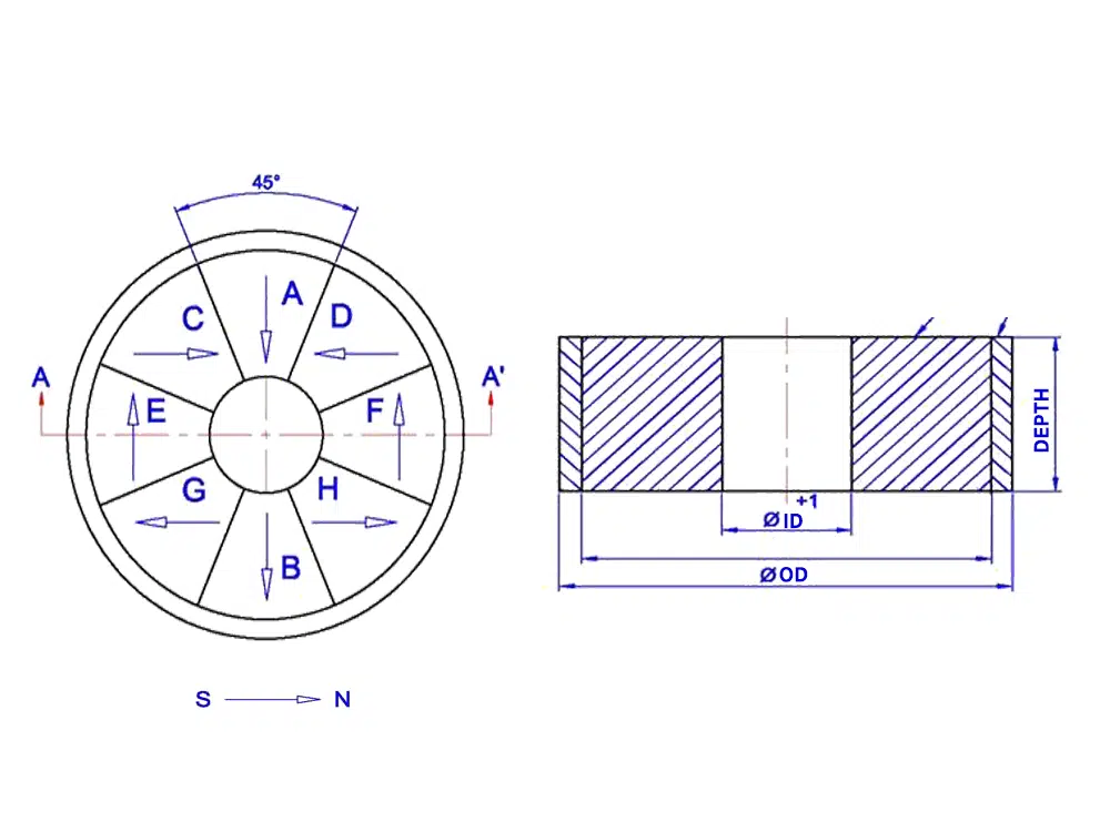
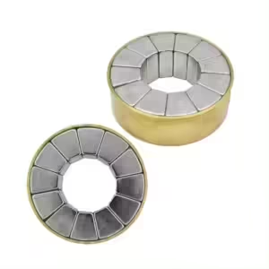
NdFeB segments can be arranged in circular or linear Halbach assemblies. The field at the working point depends on the grade, segment geometry, magnetization direction, gaps, and surrounding parts. We review the target field, housing or sleeve material, and mounting method against each drawing.
Reference configurations
Dimensions: OD × ID × depth (mm)
ES835 · N45
105 × 30 × 40
ES835-60 · N45
220 × 60 × 75
ES835-40 · N48
115 × 40 × 40
ES835-50 · N52
220 × 50 × 40
These configurations are quoted individually. Send the model or drawing, target field location, operating temperature, and expected quantity. Final specifications and availability are confirmed in the quotation.
A Halbach array is a sequence of permanent-magnet segments with changing magnetization directions. A linear layout can strengthen the field toward one face and reduce it on the opposite face; a cylindrical layout can shape the field within or outside its bore. Real assemblies have finite dimensions and segment gaps, so field strength and leakage should be specified at a particular location and checked for the actual geometry.
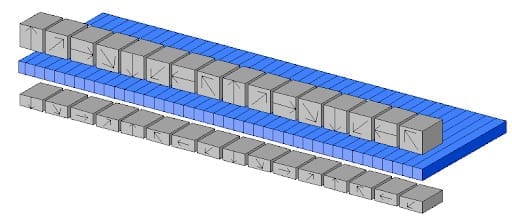
Halbach layouts are considered when a project needs a particular field pattern within a limited space. Whether they improve the finished system must be checked against its geometry, load, temperature, and measurement method.
Designers may compare segmented Halbach rotors with other magnet arrangements for the required air-gap field. Torque, efficiency, and loss depend on the full machine design; an array layout alone does not establish them.
A directed field can be useful in a moving or suspended system. Define the working gap, load, field profile, mechanical restraint, and any nearby parts before selecting an array.
Researchers use permanent-magnet arrangements to shape measurement fields. State the target field location, uniformity or gradient, allowable stray field, and validation method. A magnet assembly by itself is not a certified medical device.
For a quotation, send the drawing and field requirements so the proposed geometry can be reviewed for your application.
A useful drawing shows more than the outer dimensions. It should identify the field to be achieved, where it is measured, and the constraints that keep the segments in place.
If some values are still open, note the uncertainty in your inquiry and attach the current drawing. The final geometry and acceptance criteria should be agreed before an order is placed.