46e4b6d9-3862-4652-a5a2-4dc8c5f0146b

Magnetic compounds · Molded geometry · Drawing review

Custom injection molded magnets

Define the magnetic part and its interfaces

Injection molded magnets combine magnetic powder with a polymer binder in a molded part. For a custom design, Magnetstek reviews the proposed compound, geometry, magnetization and operating conditions before confirming feasibility and a quotation.

Send the drawing or model, critical fits, target field and quantity. Include any inserts, shafts or mating components so the material and tooling requirements can be discussed together.

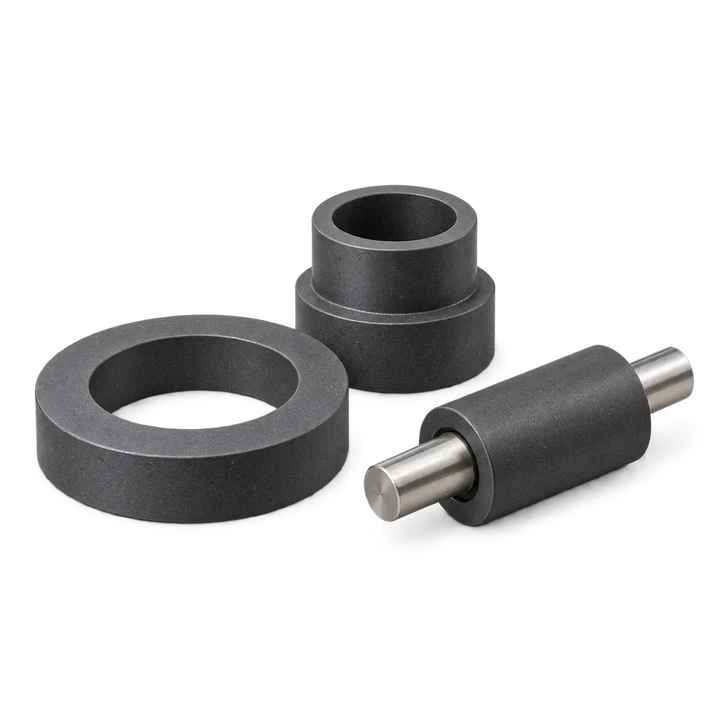
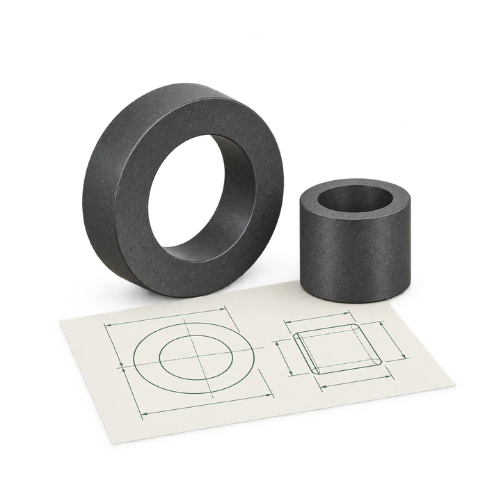
Illustrative molded magnetic rings and sleeve with shaft
AI-generated shape and interface concept. Compound, dimensions and pole pattern are confirmed for the proposed part.

Show the magnet with its mating parts

Identify the working gap, locating surfaces, bore and any insert. Mark the relationship between the magnetic poles and the mechanical reference features on the drawing.

Request A Quote
*Company e-mail address is preferred. 

Compound & geometry

Review the powder, polymer and part together

Start with the magnetic requirement

NdFeB, ferrite and SmCo powder systems offer different material options. A molded compound’s properties also depend on its binder, powder loading and orientation.

Provide an existing grade or compound callout if your drawing specifies one. Otherwise, describe the required field, flux or torque and its measurement conditions so a proposed material can be reviewed.
Compare bonded magnet forming routes →

Include the polymer and interfaces

Polyamide and PPS are examples of binders used in magnetic compounds. Selection needs the proposed material data and the part’s thermal, moisture, chemical and mechanical conditions.

For a design involving inserts, show the shaft, bushing or housing dimensions, locating features and required fit. Confirm the material combination and tooling scope with the drawing review.

What to specify

Six inputs for an injection molded magnet quotation

Mark the drawing revision, critical dimensions and pole pattern. Include the mating-part interfaces and the conditions used for magnetic acceptance.

Molded magnet drawing preparation concept
AI-generated drawing preparation concept.

Drawing & critical fits

Provide the revision, dimensions, tolerances, wall sections, bores and locating surfaces. Mark which dimensions are critical in the assembly.

Compound requirements

State a mandatory powder, polymer or compound grade if known. Identify requirements that can be reviewed with an alternative.

Inserts & mating parts

Show any shaft, bushing, housing or other component. Define interfaces, assembly loads and the proposed supply scope.

Pole pattern & output

Mark pole faces, pole count, orientation and an angular reference. Specify the field or torque target and where it is measured.

Service conditions

Include continuous and peak temperature, duration, cycling, moisture, chemicals, load and any protective finish or housing.

Quantity & acceptance

Give sample and production quantities, tooling constraints, inspection checks and required records. Confirm price and delivery with the quote.

Application review

Connect the part to its magnetic function

For a sensor, encoder or small motor design, specify the field or torque needed at the working gap and show how the pole pattern aligns with the assembly. For a rotor, include the shaft interface, retention, speed, balance and temperature requirements.

Use the rotor and arc magnet review to prepare the assembly information. Material and manufacturing scope are confirmed from the drawing.

Geometry concepts

Use the shape to start the drawing review

These concepts show the features to define in an RFQ. The proposed compound, forming details and pole arrangement need review for the finished part.

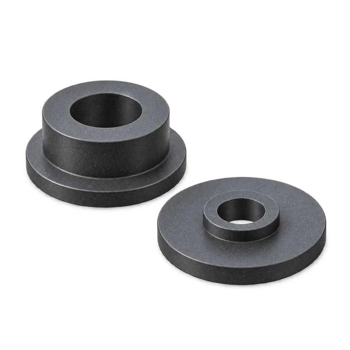
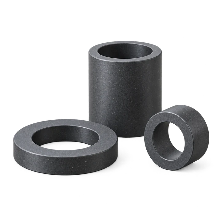
Injection molded ring and sleeve geometry concepts

Rings & sleeves

Define the bore, wall section and active magnetic surface. Mark the pole pattern and the working gap.

Discuss this geometry
Stepped and flanged molded magnet geometry concepts

Stepped & flanged features

Show locating shoulders and critical fits. Review the molding geometry and measurement conditions together.

Discuss this geometry
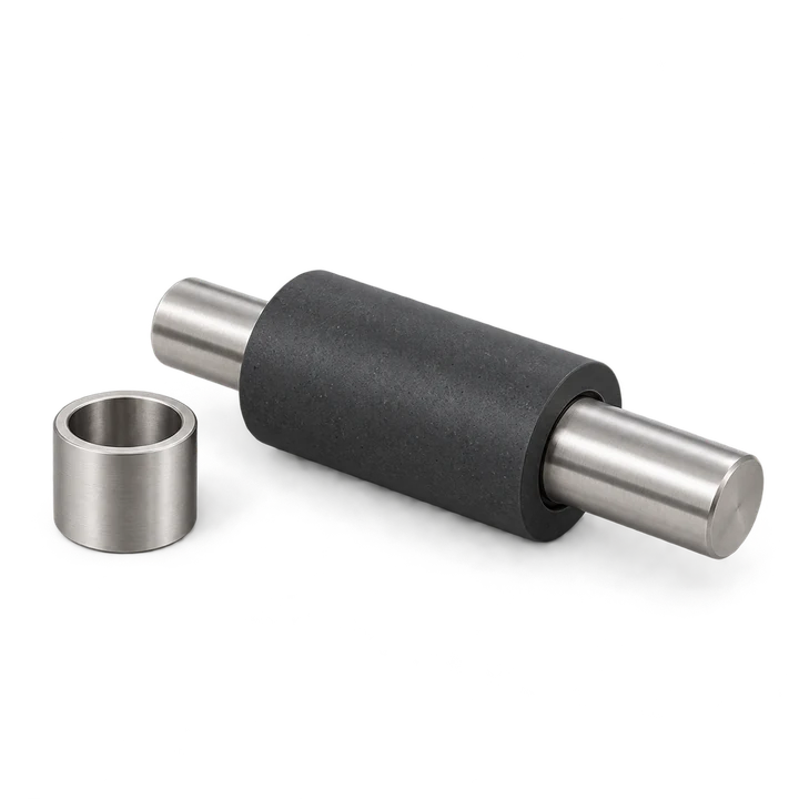
Molded magnetic sleeve and shaft interface concept

Shaft & insert interfaces

Provide the mating-part drawing, alignment surfaces and retention requirements for an assembly review.

Discuss this geometry
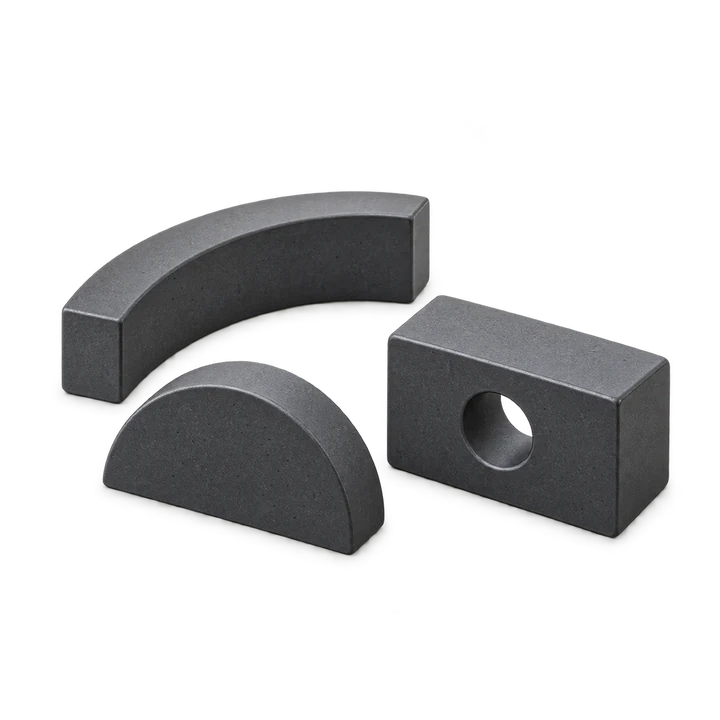
Drawing-defined molded magnet shape concepts

Drawing-defined shapes

Use a drawing or model to describe the outline, holes and mating surfaces for feasibility review.

Discuss this geometry

AI-generated geometry illustrations; they do not identify a supplied grade or an available stock item.

Technical reference

Injection molded magnet design details

Review the topics relevant to your part and request the supporting compound data with the quotation.

Which material data should be agreed?

Identify the proposed compound and its magnetic powder, binder and orientation. Compare remanence, coercivity and energy-product values with their units, measurement conditions and temperature.

For the finished part, agree the required dimensions, pole arrangement and magnetic output separately. List any compound datasheet or temperature-dependent demagnetization curves needed for the review.

How do isotropic and anisotropic materials differ in the review?

Confirm whether the proposed material needs magnetic orientation during forming and how that orientation relates to the final pole pattern. Review the material, tooling and magnetization requirements together.

A ring or shaped-part name leaves the pole arrangement open. Mark the intended poles and their relationship to any mechanical reference on the drawing.

How should geometry, shrinkage and tolerances be handled?

Identify critical fits, wall sections, holes, ribs and mating surfaces. Discuss the dimensions and measurement conditions for the proposed compound and tooling.

Consider the effect of molding shrinkage, conditioning and the operating environment on the finished dimensions. Confirm achievable tolerances through the part review and the agreed sample inspection.

What information is needed for an insert or shaft?

Provide the insert material, drawing, dimensional limits and required location in the molded part. Define assembly loads, retention requirements and the surfaces used for alignment.

Clarify whether the request covers a magnet alone or a proposed assembly. Review the interface and inspection plan before confirming the tooling or manufacturing scope.

What determines service temperature?

Review the magnetic powder, binder, geometry and complete exposure cycle. Include continuous and peak temperature, duration, opposing fields and the working point.

State the test method and conditions behind any physical-property value, including heat-deflection data. Agree which material limits and finished-part tests are relevant to the actual service conditions.

How should moisture and chemical exposure be specified?

Describe humidity, liquid or chemical contact, cleaning and expected exposure duration. Include any protective coating, encapsulation or housing and its dimensional allowance.

Confirm the proposed compound’s environmental data and the acceptance test. Define the conditioning used for dimensional and magnetic measurements where it matters.

How should a sensor or multipole part be checked?

Specify the pole count, active surface, pole sequence and angular reference. Show the sensor position, working gap and mating components.

Agree the field, flux or waveform requirement, fixture, measurement location and allowed range. Use the same conditions when comparing samples and later deliveries.

Magnetization direction reference →
Which records belong in first article acceptance?

Agree the drawing revision, sample size, dimensional checks, polarity or field tests, surface condition and any environmental qualification. Identify the records required for the compound and for the finished part.

Provide applicable system or device requirements for regulated or safety-critical uses. Confirm the available documentation and supply scope before the order.

First article inspection checklist →

From drawing to quotation

Confirm the part before fixing the tooling scope

  1. Step 1

    Send the requirement

    Provide the drawing, magnetic function, interfaces, operating conditions and quantity.

  2. Step 2

    Review the proposal

    Discuss compound, geometry, inserts, orientation, magnetization and tooling requirements.

  3. Step 3

    Agree sample checks

    Confirm critical dimensions, magnetic acceptance, conditioning and the required records.

  4. Step 4

    Confirm the quotation

    Review specifications, tooling terms, quantities, price and delivery before ordering.

Send your molded magnet requirement

Documents & related options

Connect the drawing to the supporting data

List required compound data, magnetic curves, environmental tests and inspection records in the inquiry. Confirm their applicability to the proposed part and availability with the order.

Drawing preparation

Collect the geometry, magnetic function and operating conditions.

RFQ checklist →

Bonded magnet routes

Compare the forming route against the required part and quantity.

Bonded magnets →

Technical context: thyssenkrupp’s plastic-bonded NdFeB material reference and NTN Advanced Materials’ sensor magnet comparison. Their material and test information illustrates how properties are specified; it is not a Magnetstek product specification.