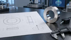
A quote-ready custom magnet drawing should define the finished part, its magnetic orientation, and the conditions under which it must work. At minimum, include the material family and grade, final dimensions and critical tolerances, magnetization direction, coating, continuous and peak temperature, magnetic acceptance criteria, quantity, and inspection requirements. The most expensive ambiguities are usually an unclear pole direction, dimensions that do not state whether they apply before or after coating, and magnetic requirements without a defined test position or method.
This guide is for design engineers, sourcing teams, and technical buyers preparing a custom permanent magnet request for quotation. It explains what to put on the drawing, what belongs in the supporting specification, and which details should be reviewed with the supplier before tooling or production begins.

Custom magnet drawing checklist
| Specification area | What to provide | Why it matters |
|---|---|---|
| Material | NdFeB, SmCo, ferrite, AlNiCo, bonded magnet, or an approved alternative | Material affects magnetic output, temperature behavior, corrosion resistance, mechanical behavior, and cost |
| Grade | Required grade or the magnetic properties that must be achieved | A grade name alone may not describe the performance needed in the finished assembly |
| Geometry | Complete dimensions, units, chamfers, radii, holes, slots, and critical interfaces | Missing geometry creates fit, tooling, inspection, and quotation uncertainty |
| Tolerances | Functional tolerances on critical features and suitable general tolerances elsewhere | Unnecessarily tight tolerances can increase processing and inspection burden |
| Magnetization | Direction, outward pole face, pole count, and any angular alignment requirement | The same magnet shape can produce a different usable field when magnetized differently |
| Coating or finish | Coating type, appearance requirement, and whether dimensions are final after coating | Coating influences corrosion protection, bonding, wear, and final fit |
| Operating conditions | Continuous and peak temperature, humidity, fluids, vacuum, shock, and vibration | Application conditions can change the appropriate material, grade, coating, and assembly method |
| Magnetic acceptance | Property, target or limit, test location, air gap, fixture, temperature, and method | Surface field, flux, pull force, and material properties are not interchangeable measurements |
| Quality and logistics | Quantity, prototype plan, inspection report, traceability, marking, and packaging | These requirements affect the production and quotation route |
This checklist is a starting point rather than a universal specification. A simple holding magnet, a sensor magnet, and a high-speed rotor segment may require very different drawing controls.
Define the application before freezing the magnet
A magnet is part of a magnetic and mechanical system. Its performance depends not only on material and size, but also on the air gap, nearby steel, mating component, orientation, operating temperature, and load direction. If those system conditions are still flexible, state the required outcome instead of locking the supplier into an unverified magnet design.
For example, “N52 disc magnet” is not a complete functional requirement. A supplier cannot determine from that phrase alone whether the application needs a holding force against steel, a specified field at a sensor location, a compact rotating field, or resistance to demagnetization at an elevated temperature. A better request describes the available envelope and the performance target at the actual working position.
When the geometry is already fixed, the drawing becomes the controlling definition of the part. When the design is still open, provide both the current drawing and the application constraints so material, grade, dimensions, and magnetization can be reviewed together.
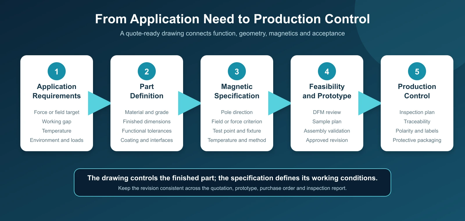
Twelve details to include in a custom magnet specification
1. Material family and permitted alternatives
Identify the intended material family: sintered NdFeB, SmCo, ferrite, AlNiCo, bonded NdFeB, injection-molded magnet material, or another defined option. Do not use “rare earth magnet” as the only material description because both NdFeB and SmCo are rare-earth magnet families with different design characteristics.
If substitutions are acceptable, say what may change and what must remain fixed. An approved alternative should be evaluated against the required magnetic properties, temperature, corrosion environment, geometry, and qualification plan rather than treated as a name-for-name replacement.
2. Grade or required magnetic properties
For NdFeB, a designation such as N42, N42H, or N35SH communicates a property range and temperature-related grade family. The highest energy-product number is not automatically the best choice. Intrinsic coercivity, temperature, magnet geometry, and the working point of the magnetic circuit can be more important to stability than the headline grade number.
If the application is sensitive to material properties, identify which values require documentation. Depending on the project, these may include remanence, coercivity, intrinsic coercivity, maximum energy product, or a demagnetization-curve requirement. Link the requirement to an agreed material specification and measurement method. Magnetstek’s NdFeB magnet grade data can be used as a starting point for grade review, but the quotation should confirm the exact property range and documentation for the part.
3. Finished geometry and units
Dimension the complete finished magnet. Include all diameters, lengths, thicknesses, inner diameters, angles, arc dimensions, slots, steps, counterbores, countersinks, chamfers, and radii needed to define the part. State the units and drawing scale, but do not rely on scaling the drawing to recover an omitted dimension.
For rings and tubes, identify both inner and outer diameter requirements. For arc segments, define the radii, angle, length, thickness, and orientation. For irregular parts, provide enough views or a controlled 3D model to remove geometric ambiguity.
4. Functional tolerances
Apply tight tolerances where fit or function requires them. Examples include a bore that locates on a shaft, a thickness that controls an air gap, or a face that establishes sensor distance. Use practical general tolerances for noncritical features.
Permanent magnet materials are hard and brittle, and many sintered magnets are finished by grinding. Tolerance feasibility depends on the material, part size, wall thickness, geometry, coating, measurement method, and quantity. Avoid copying metal-machining tolerances onto every feature without reviewing whether they are necessary and measurable.
5. Datums and geometric controls
If orientation, concentricity, runout, flatness, parallelism, or true position affects assembly performance, define a datum scheme and the relevant geometric control. The purpose is to communicate functional relationships, not to decorate the drawing with extra symbols.
Use one stated drawing standard consistently. ASME describes Y14.5 as the authoritative guideline for communicating geometric dimensioning and tolerancing on engineering drawings and digital product definitions. A supplier should not have to guess which interpretation system applies.
6. Magnetization direction and pole reference
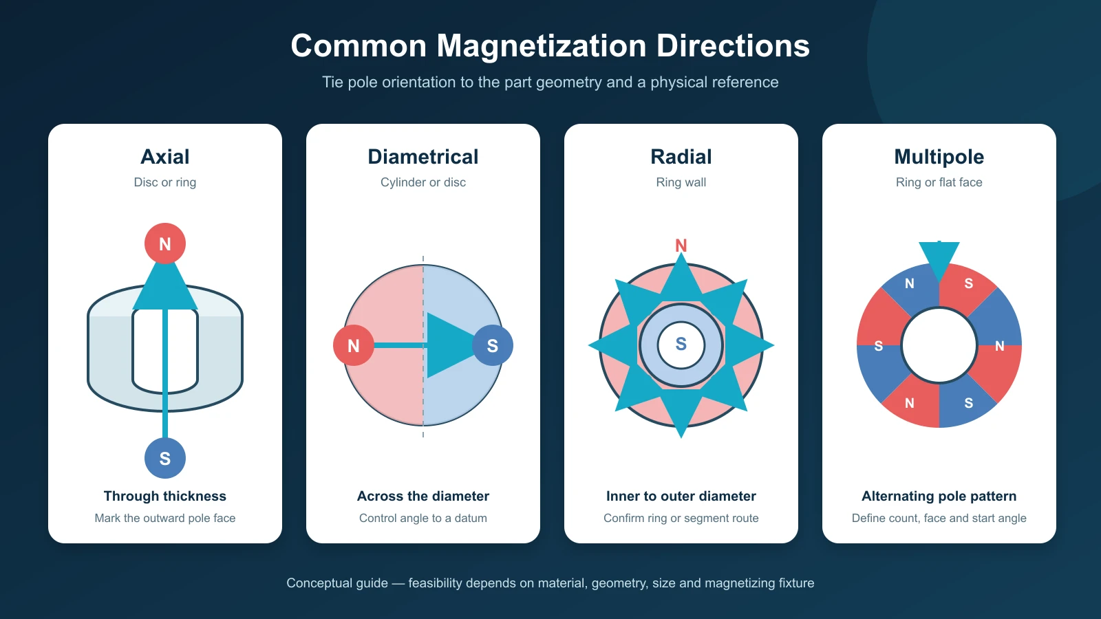
Show the magnetization direction graphically and describe it in words. Common options include axial magnetization through the thickness, diametrical magnetization across a diameter, radial magnetization through a ring wall, and multipole patterns. The available options depend on the material, geometry, size, pole count, and magnetizing fixture.
For an axially magnetized disc, state which flat face should present north if assembly orientation matters. For a diametrically magnetized cylinder, define the pole axis relative to a datum, slot, flat, keyway, or mark when angular alignment is required. For multipole rings, specify pole count, pole sequence, reference angle, and whether the poles are on the inner diameter, outer diameter, or face. See Magnetstek’s magnetizing direction guide for common configurations.
7. Continuous and peak operating temperature
State both the normal continuous temperature and any short-duration peak. Also describe nearby heat sources, thermal cycling, and cooling conditions. A published maximum working temperature is not a guarantee for every magnet geometry or magnetic circuit. The risk of irreversible demagnetization depends on the material curve, magnet shape, operating point, applied opposing field, and time-temperature history.
If temperature is uncertain, ask for a grade review rather than selecting a suffix from temperature alone. Prototype or assembly-level validation may be needed for critical applications.
8. Coating and environmental exposure
For NdFeB, define the intended surface protection and the environment it must withstand. Relevant conditions may include indoor humidity, condensation, salt, cleaning agents, oils, fuels, vacuum, sterilization, or direct contact with an adhesive or overmold material.
State whether all dimensions and tolerances apply to the final coated part. Coating buildup can be important on small bores, thin air gaps, press interfaces, and tightly fitted parts. Appearance-only descriptions such as “silver” or “black” are not complete coating specifications. Review the available NdFeB magnet coating options and confirm the final system for the quoted part.
9. Magnetic acceptance criteria
Specify the measurement that represents function. Common choices include material properties measured on a sample, total magnetic flux, magnetic moment, surface flux density at a defined point, field at a working distance, or pull-off force in a controlled fixture. These values answer different questions and should not be substituted without review.
A magnetic requirement needs a location and method. For a field measurement, define the sensor type or probe orientation, distance from the surface, temperature, and reference position. For pull force, define the target material and thickness, contact condition, pull direction, separation speed, and whether any coating, paint, film, or air gap is present. If the application uses magnet-to-magnet attraction, say so; a magnet-to-steel test is a different magnetic circuit.
10. Mechanical interface and assembly method
Describe how the magnet will be retained and loaded. Indicate whether it will be bonded, clamped, overmolded, potted, captured in a housing, mounted with a screw, or installed in a rotor. Show the mating geometry and identify any shear, impact, vibration, or centrifugal load.
Do not assume a brittle sintered magnet can serve as a structural fastener. Avoid undefined interference fits and point loads. If adhesive bonding is planned, identify the adhesive system or at least the substrate, cure conditions, bond-line constraints, and surface-preparation limits so coating compatibility can be reviewed.
11. Prototype and production quantities
Provide separate prototype and expected production quantities. Quantity can affect the preferred manufacturing, magnetizing, inspection, and packaging route. Also identify which requirements are fixed and which may be adjusted during design for manufacturability review.
If samples are required before production, define what the sample is intended to prove: fit, magnetic performance, coating, assembly process, environmental durability, or all of these. A sample plan is more useful when it has clear acceptance criteria.
12. Inspection, traceability, marking, and packaging
List the documents and inspections required with the shipment. These may include a dimensional report, magnetic test results, material certification, coating documentation, polarity confirmation, lot identification, or a sample retention requirement. Request only the records needed for the project’s risk and quality system.
Strong magnets can attract each other during handling and transport. Define orientation trays, spacers, pole-pair packaging, protective separators, labels, or unit packs when they are needed for safe assembly and identification. If north and south variants are supplied, require unambiguous part numbers and package labels.
How to show magnetization on the drawing
Magnetization should be understandable without relying on color alone. Use arrows, N and S labels, section views, a pole map, and a written note as appropriate.
- Axial disc or ring: show the magnetization axis through the thickness and identify the outward pole face when polarity matters.
- Diametrical cylinder or disc: show the pole axis across the diameter and control its angle to a datum when the field must align with another feature.
- Radial ring: identify whether the outer diameter is north or south and confirm whether a truly radially oriented ring or an assembled segment solution is intended.
- Multipole ring or face: show the number of pole pairs, active surface, starting pole, sequence, pitch, and angular reference.
- Matched pairs: state whether parts are supplied as attracting pairs and define the outward pole of each part number.
When pole position is critical, include the permitted angular deviation and the inspection reference. A generic note such as “magnetized” does not define the field orientation.
Specify force or field under real working conditions
Catalog pull-force values are meaningful only with a defined test setup. Magnetstek’s pot-magnet tables list reference pull-off values; the steel target, thickness, surface condition, air gap, pull direction, and measurement method should be confirmed for the specific quotation. A value measured under one setup may not represent the customer’s actual assembly.
For a custom design, provide the actual magnetic circuit whenever possible:
- Required force or field and the allowable range
- Working distance or air gap
- Mating magnet or steel geometry and material
- Available magnet envelope
- Load direction: direct pull, shear, torque, or another condition
- Operating temperature and surrounding ferromagnetic components
- Whether a steel yoke, backing plate, or housing is part of the design
If the requirement is safety-critical, the magnet should not be the only load-retaining feature unless the complete system has been engineered and validated for that purpose.
Example of a quotation-ready magnet specification
| Item | Example information |
|---|---|
| Part | Custom ring magnet according to drawing revision B |
| Material | Sintered NdFeB; supplier may propose an alternative grade for review |
| Grade | N42H preferred; final selection subject to thermal and demagnetization review |
| Dimensions | OD, ID, thickness, chamfers, and tolerances as shown; all dimensions apply after coating |
| Magnetization | Axial through thickness; north pole on the marked face |
| Coating | Supplier recommendation for the stated humidity and adhesive system |
| Temperature | Provide continuous and peak assembly temperatures |
| Magnetic requirement | Define field or force target, test position, fixture, gap, and temperature |
| Application | Describe the assembly, mating components, load direction, and available space |
| Quantity | Prototype quantity and estimated annual production quantity |
| Inspection | Dimensional report, polarity confirmation, and agreed magnetic test result |
| Files | Controlled 2D PDF drawing plus STEP model if geometry requires it |
The example deliberately leaves project-specific numbers blank. Do not reuse a grade, coating, tolerance, or test limit from another design without checking the new operating conditions.
Common RFQ mistakes
- Requesting the strongest magnet without defining the application. Strength can mean material energy product, surface field, flux, holding force, torque, or field at a distance.
- Leaving magnetization direction to assumption. Identical dimensions can behave differently when the pole orientation changes.
- Applying tight tolerances everywhere. Control the dimensions that affect fit and function, and review the rest for manufacturability.
- Not stating whether dimensions are after coating. This is especially risky for small holes, thin parts, and narrow air gaps.
- Using a pull-force number without test conditions. A value without the target plate, gap, direction, and method cannot be compared reliably.
- Ignoring peak temperature and opposing fields. Both can affect the margin against irreversible demagnetization.
- Sending a 3D model without a controlled drawing. The model may define geometry, but it may not define tolerances, material, coating, pole orientation, inspection, or revision status.
- Omitting prototype and production quantities. The supplier cannot select the most appropriate production route without volume context.
Questions to resolve before approving production
- Does the quoted material and grade meet the temperature and demagnetization requirements of the actual magnetic circuit?
- Are all controlled dimensions final after coating?
- Is the magnetization direction feasible, and is pole orientation tied to a physical datum or mark?
- Which dimensions and magnetic characteristics will be inspected, and by what method?
- Does the prototype test represent the production assembly, including air gaps and nearby steel?
- Are coating, adhesive, housing, and cleaning processes compatible?
- Are north and south variants, matched pairs, and packaging labels impossible to confuse?
- Is the drawing revision consistent across the purchase order, quotation, samples, and inspection documents?
Frequently asked questions
Is a 3D model enough to quote a custom magnet?
Usually not by itself. A 3D model can define geometry, but the quotation still needs material, grade or magnetic requirements, tolerances, magnetization, coating, operating conditions, quantity, and inspection requirements. A controlled 2D drawing and supporting specification reduce ambiguity.
Should magnet dimensions be specified before or after coating?
For assembly control, finished dimensions are normally the most useful. State explicitly whether each dimension and tolerance applies before or after coating. If coating buildup could affect a bore, air gap, or mating feature, discuss the measurement and acceptance method with the supplier.
Do I need to specify both grade and pull force?
They describe different things. Grade refers to a range of material properties, while pull force is the result of a particular magnet geometry and test circuit. If holding performance matters, define the application or the pull-force test conditions in addition to the material requirement.
How do I specify polarity for magnet pairs?
Create separate part numbers or variants and identify the outward pole face of each. State that the parts must be supplied as attracting pairs, and use labels or packaging that prevent north-facing and south-facing versions from being mixed.
What files should I send with an RFQ?
Send a controlled PDF drawing, a STEP or other neutral 3D model when geometry is complex, the application and environmental requirements, prototype and production quantities, and the required inspection documents. Follow the custom magnet ordering process and keep the revision level consistent across every file.
Prepare the drawing for engineering review
Before requesting a quotation, review the drawing as a manufacturing and acceptance document, not only as a geometric model. The supplier should be able to identify the finished part, understand the magnetic orientation, evaluate the environment, and determine how conformity will be measured.
Magnetstek supplies custom neodymium magnets and other permanent magnet materials. For a feasibility review, send the controlled drawing, application conditions, magnetic target, and quantity. Final material, grade, dimensions, tolerances, coating, testing, documentation, and availability should be confirmed in the specific quotation.
Technical references
- ASME Y14.5 Dimensioning and Tolerancing – rules and practices for communicating dimensions, tolerances, datums, and geometric controls.
- IEC 60404-5 Permanent Magnet Materials Methods of Measurement of Magnetic Properties – standardized measurement principles for magnetically hard materials.
- ASTM Committee A06 Subcommittee A06.01 – includes ASTM A977/A977M for hysteresigraph measurement of high-coercivity permanent magnet materials.
- Magnetstek Magnetizing Direction – common pole orientations for discs, cylinders, blocks, rings, and arcs.
- Magnetstek Magnet Pull Force Guide – a reference showing why pull-force values need stated test conditions.