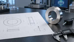
A custom sensor magnet can pass a surface-field check and still fail in the finished assembly. The sensor reads the field at its own active area, after the magnet has been placed behind plastic, adhesive, a cover, or a housing. A small change in that distance can move a marginal design across a switching threshold. Before approving a prototype, define the field you need at the sensor and the conditions under which you will measure it.
Read the sensor data sheet first
“Use a stronger magnet” sounds like a simple fix. It may solve a weak signal, but it can also drive a linear or angle sensor outside its useful field range. The first useful numbers come from the sensor data sheet: the magnetic component it detects, its operating range, and any switching or release thresholds. A Hall switch and a rotary angle sensor can require very different magnetic arrangements.
Texas Instruments explains that the direction of the field vector matters to a Hall sensor, along with magnet size, material, and proximity. Its magnet selection guidance for Hall sensors is a useful reminder to check the component the IC actually measures. For a switching device, also compare the proposed field with the data sheet’s operate and release limits, including their stated tolerances. For a linear device, check the usable span rather than a single trigger point.
Once those limits are clear, a supplier can discuss geometry, material, magnetization, and process capability against a real target. For a custom sensor magnet, a grade designation alone does not specify the field at the sensor.
Define the custom sensor magnet working gap
Draw the magnet, sensor package, PCB, and any intervening parts in one cross-section. Mark the distance from the magnet surface to the sensor’s active area, not just the visible face of the package. That distinction is easy to miss when the package is buried behind a cover or mounted on the opposite side of a board. Allegro calls this the total effective air gap.
Record three positions: the closest permitted gap, nominal gap, and largest permitted gap. Use the mechanical tolerance stack to find them. Include the parts that will exist in production: adhesive thickness, molded wall, coating, board placement, shaft play, or an assembly stop, as applicable. If the magnet moves, describe its path and the point in travel where the measurement matters.
For an angle sensor, the gap is only part of the story. Tilt and eccentricity can change angular error. Infineon’s magnetic design tool for angle sensors explicitly treats air gap, tilt, and offset as separate inputs. The same habit is useful in a prototype review: write down the alignment limits instead of assuming the centered sample represents every assembly.

Specify direction as carefully as strength
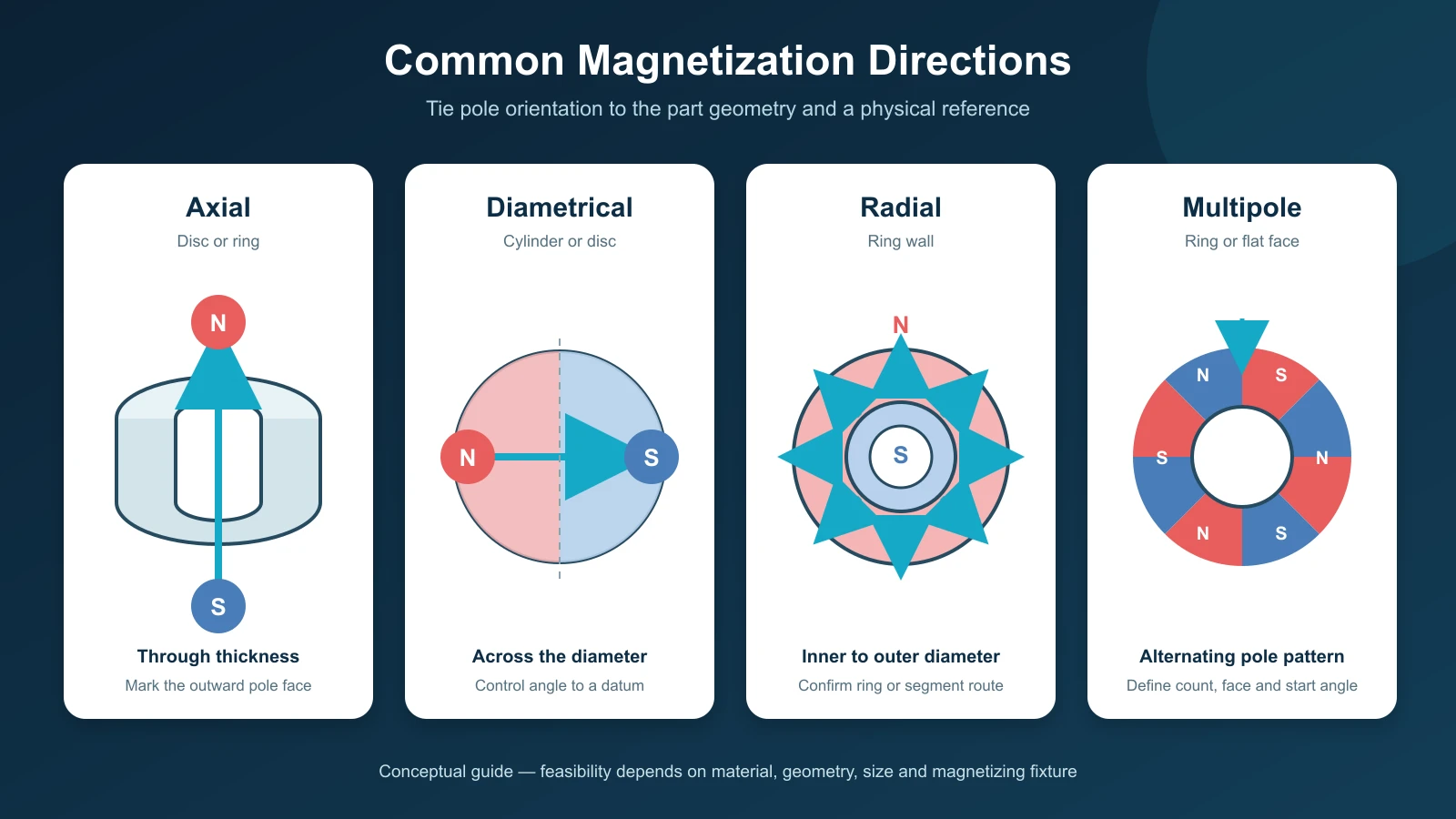
A drawing that says “N42 disc magnet” leaves out a critical instruction. Is the magnet axially or diametrically magnetized? Which face or edge points toward the sensor? For a rotating shaft, where is the pole reference relative to a mechanical datum? Those details affect both the field component and the output signal.
Use a simple coordinate sketch. Label the magnetization direction, the sensor’s sensitive axis, and the measurement location. If the application uses two or three magnetic axes, specify which component or vector magnitude will be accepted. “Surface gauss” is too vague for an assembly test: it does not say where the probe sits, which way it faces, or whether nearby steel is present.
Where polarity is important, include a physical orientation mark or an assembly instruction that can be checked. A correctly sized magnet installed with the wrong pole toward a unipolar switch will not behave like the approved sample.
Ask for a small field map
One measurement at nominal position can hide a weak edge case in a custom sensor magnet. For a first prototype, request a short matrix instead: field at minimum, nominal, and maximum working gap; field after the expected lateral offset; and output at the travel positions that decide whether the product passes. If temperature is significant, repeat the relevant checks at the temperature limits of the actual application. Choose the points from the design, rather than filling a test report with measurements that do not affect a decision.
For a rotary sensor, the useful result may be a field trace over one revolution and the sensor’s angle error, not a peak field value. Allegro’s angular sensor application note shows how both air gap and alignment affect performance. In a switch application, measure around the actual operate and release positions, where a small change has the greatest practical effect.
A field map does not need to be elaborate. A labeled sketch, a table of measured positions, and the sensor output recorded beside each value are often enough to reveal whether the design has margin.
Example: a lid-position switch
Consider a lid-position switch with a magnet embedded in a molded cover and a Hall IC on a PCB. A bench prototype switches cleanly at its nominal position. Later, a thicker wall and a different adhesive layer increase the production gap. The approval test should place the magnet at the largest allowed closed-lid gap and check that the sensor changes state before the latch reaches its stop. It should also check the opening position, where the switch must release. Both positions need clear mechanical datums.
If one sample fails, measure the field at the sensor plane and record the actual wall and adhesive thickness before ordering a stronger grade. That short comparison may show whether the issue is magnetic variation or a changed assembly gap. The same test logic applies to sliding and rotary mechanisms.
Make the prototype test repeatable
For a custom sensor magnet, use a fixture that sets probe position and orientation. State whether measurements are taken on a loose magnet, in a partial assembly, or in the complete product. Ferromagnetic brackets, screws, and return paths can alter the local field, so the final assembly is the reference when it changes the magnetic circuit. Record the instrument, measurement axis, gap datum, temperature, and sample orientation in the report.
Keep electrical testing and magnetic testing linked. If the sensor output fails, the field measurement at that same position helps distinguish a magnetic shortfall from a sensor, calibration, or placement issue. Retesting a loose magnet on a steel bench can produce a number, but it may not answer the assembly question.
When a prototype passes, retain the drawing revision and the test setup with the approved sample. The sample is useful evidence only if the later production lot is evaluated by the same acceptance method.
Agree on acceptance before production
A workable custom sensor magnet acceptance note names the measurement and its limits. It can be short. The point is to remove interpretation when a new lot arrives.
| Item | Write down |
|---|---|
| Geometry | Finished dimensions, coating, datum surfaces, and assembly position |
| Magnetization | Axis, pole orientation, and any orientation mark |
| Field check | Field component, probe position, axis, gap, fixture, and allowed range |
| Functional check | Sensor output or switching position at the chosen test points |
| Conditions | Temperature, surrounding parts, and sampling plan |
Do not copy a field limit from a catalog magnet unless the geometry and test method match your assembly. If the sensor manufacturer gives a recommended input range, use that alongside a tolerance analysis and measured prototypes to set project-specific limits. Leave room for production variation without accepting a part that fails in the device.
A concise brief for a custom sensor magnet RFQ
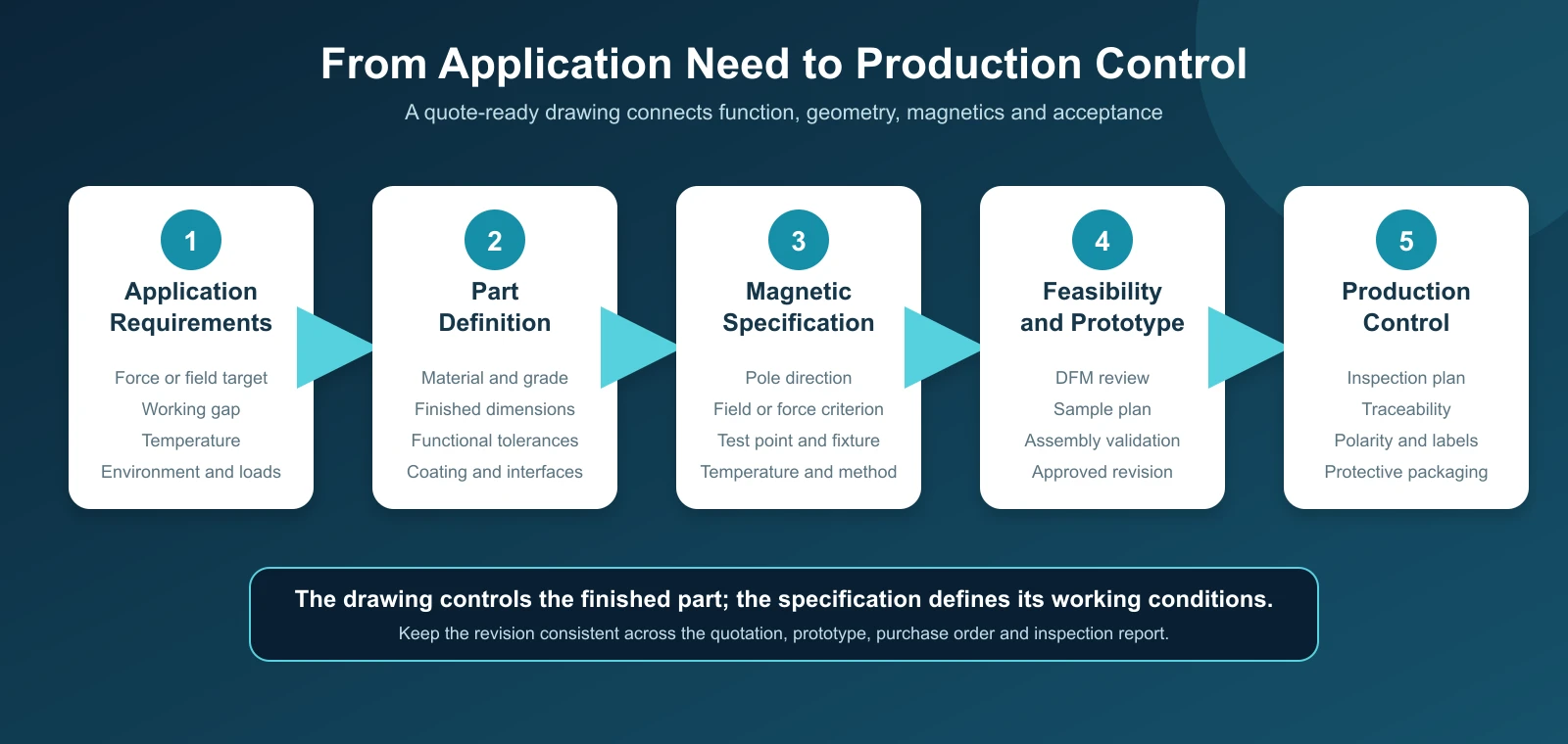
If you are sending a design for review, the most useful package is a magnet drawing plus one page on how it works in the product. Include the sensor part number and data sheet, a cross-section with minimum and maximum working gap, the magnetization and polarity, operating temperature, nearby ferromagnetic parts, prototype quantity, and the field or functional acceptance method. State what is fixed and what the supplier may propose changing. For the general drawing requirements, see our custom magnet drawing guide.
Magnetstek can review a custom magnet request against those assembly conditions. If your current sample is close but unreliable, send the drawing and the failed test position through the contact form. The gap and test result usually tell more than the grade printed on the purchase order.
A field-test record for a custom sensor magnet
When a custom sensor magnet sample arrives, put the drawing and test record on the same bench. The report should let someone who was absent from the prototype meeting reproduce the check. A photograph of the setup helps, but it cannot replace dimensions and a defined probe axis. If you use a Hall probe, note which face is its sensing face and how it is held. If you read the field through the installed IC, record the device settings and the raw output as well as the interpreted result.
The following fields work as a one-page starting point. Fill them with your own limits; the table is a record format, not a set of universal magnet tolerances.
| Record field | What the reviewer needs to see |
|---|---|
| Part identity | Magnet drawing revision, sample or lot ID, material, coating, and magnetization direction |
| Sensor identity | IC part number, board revision, sensitive axis, and package orientation |
| Fixture | Assembly state, reference surfaces, spacers, surrounding steel, and probe or IC position |
| Gap | Measured minimum, nominal, or maximum condition and how each was established |
| Magnetic reading | Signed Bx, By, or Bz component as applicable, instrument, and unit |
| Functional result | Switch state, release point, linear output, or angle error at the same position |
| Environment | Temperature and any conditioning relevant to the product |
| Decision | Specified limit, measured result, pass/fail, date, and reviewer |
Keep raw readings in the record. “Pass” alone is difficult to investigate when a later assembly behaves differently. The important comparison is between samples tested at the same physical point, with the same field component and fixture. A supplier can then separate a part issue from a change in the customer’s assembly.
Surface field and installed field answer different questions
For a custom sensor magnet, a surface-field measurement can be a useful production screen once it has been correlated with the device. It is quick to collect on a loose part, and it can flag a magnet with the wrong orientation or an obvious process shift. It cannot, by itself, account for the cover wall, sensor-package depth, or a steel return path in the device. For initial qualification, pair the loose-part check with the installed field and functional output.
After several acceptable samples have been measured both ways, the team may decide that a simpler incoming check is adequate. Document the correlation and its limits. If geometry, housing material, sensor IC, or gap changes, revisit that decision. A convenient inspection number is only useful while it predicts the behavior you care about.
What to do when two prototypes disagree
First put both samples in the same fixture. Check the physical gap rather than relying on the nominal drawing dimension. Confirm pole orientation with a marked reference, then measure the field component at the sensor location. Finally, compare the sensor output at the same position. This sequence is intentionally mundane: it prevents a different probe angle, a misplaced spacer, or a reversed magnet from being mistaken for a material problem.
If the fields differ while geometry matches, ask for the magnet’s actual dimensions and magnetization inspection result. If the fields match but the outputs differ, review sensor placement, electrical configuration, and calibration. If a steel bracket was added between revisions, test with that bracket installed. Each finding points to a different corrective action, so keep the observations separate in the report.
Carry the approval method into the next lot
When you approve a custom sensor magnet prototype, identify what is frozen and what can still change. Save the approved magnet drawing, assembly cross-section, sensor data sheet revision, fixture sketch, test procedure, and a few representative readings together. State whether the supplier must provide a magnetic field report, a polarity check, dimensional inspection, or all three. Agree on the sampling plan before routine shipments begin; the right plan depends on the application’s risk and the process used to make the part.
The next custom sensor magnet lot can be checked against the same reference. Keep the measurement axis, gap datum, and temperature consistent. If the magnet geometry or coating changes, assess whether it shifts the working gap even if the nominal magnetic grade remains the same. A coating change that adds thickness at a locating face is also a mechanical change to the magnetic circuit.
For moving assemblies, retain at least the pass-critical travel positions. A single reading at the fully closed stop may miss an early or late transition that the product relies on. If the device has software calibration, record whether the acceptance test uses default settings or calibrated output. That distinction matters when a future lot arrives without the original technician present.
When geometry is the useful lever
If a custom sensor magnet produces too little field at the largest gap, increasing grade is one option, but it is not the only one. More magnet volume, a different aspect ratio, a smaller permitted gap, or a change to the magnetic return path may improve the field at the IC. If the field is excessive at the closest gap, a smaller magnet or different placement may be easier to control than a grade change. Any proposal has to be checked against the sensor’s full operating range and the physical space available.
For an angle sensor, judge the complete rotation as well as field strength at one angle. A magnet that looks strong at the center may still give poor angular behavior if it is tilted or off-axis. For a switch, watch both the operate and release positions. Ask the supplier to show the expected effect at those positions and then verify it with parts in the real assembly.
Make the handoff readable
Put the decision in plain language beside the numbers: “Approved at the maximum closed gap with the production cover installed” is more useful than “magnet OK.” Note any unresolved condition, such as a temperature test still pending or an alternate adhesive under review. If an engineering change alters a datum, have the test owner sign off on the new fixture position before comparing results with old lots.
That discipline saves time when the project moves from the engineer who built the first prototype to the buyer or quality team who receives production parts. They can use the same evidence to accept a good lot, question a borderline one, or explain a failure without guessing what the original sample test meant.
Common questions
Can I approve a custom sensor magnet from surface gauss alone?
Only if surface gauss has been shown to predict the actual sensor result for your geometry and fixture. For most new assemblies, measure at the sensor position and verify the electrical response. The two tests answer different questions.
Should I test at the nominal gap or the worst case?
Test nominal gap to understand the intended design, then test the permitted extremes to confirm margin. A prototype that passes only at nominal assembly position is not ready for a production tolerance decision.
What if my sensor works with one prototype but not another?
Check the gap, lateral alignment, polarity, and test setup before changing grades. Then compare the measured field and sensor output at the same position for both samples. That comparison makes a supplier discussion much more precise.