46e4b6d9-3862-4652-a5a2-4dc8c5f0146b

Polymer-bonded magnets · Drawing review

Custom bonded magnets

Review the powder, binder and pole pattern together

Bonded magnets combine magnetic powder with a polymer binder. For a custom part, Magnetstek reviews the forming method, finished geometry, magnetic output and operating conditions before confirming the proposed specification and quotation.

Send a drawing and describe the useful field or torque in the assembly. Material availability, tooling, quantity, price and lead time are confirmed for the individual request.

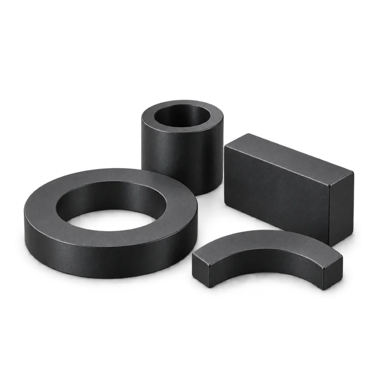
AI-generated bonded-magnet ring, sleeve, block and arc geometry concept
AI-generated bonded magnet geometry illustration. The drawing and quotation define the material, dimensions and pole pattern for your part.

Start with the assembly geometry

For a ring, specify the bore, outside diameter, height and pole faces. For a block, disc or shaped part, identify the surfaces that locate it and the gap where magnetic output is needed.

Request A Quote
*Company e-mail address is preferred. 

Process selection

Choose a forming route around the part

A bonded magnet is a composite. Its behavior depends on the magnetic powder, binder and forming process as well as the finished geometry.

Compression-bonded parts

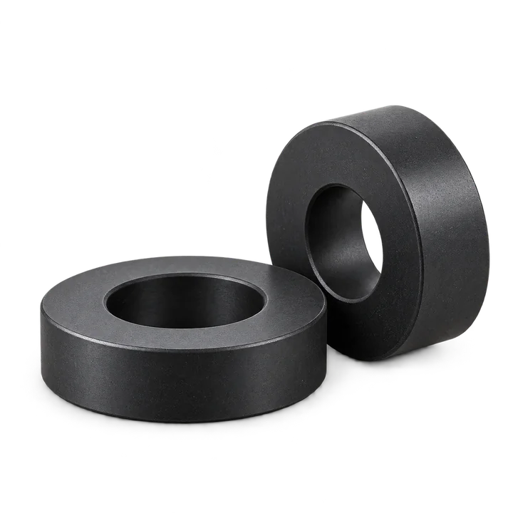
In compression bonding, a powder-and-binder compound is compacted in a die and the binder is cured. Review the geometry and magnetic requirements before selecting the compound.

Rings and other die-formed parts need a review of wall thickness, height, edge details and tooling. Requested dimensions and tolerances remain subject to confirmation.

Discuss a compression-bonded part →
Injection-molded parts

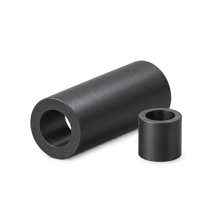
Injection molding forms a magnetic compound in a mold. The powder and polymer combination affects magnetic and physical properties.

Discuss any inserts, locating features, molding direction and assembly interfaces. Confirm the proposed material and process for the complete drawing.

Review injection-molded magnet requirements →

What to specify

Six inputs for a bonded magnet quotation

Finished dimensions

Include the drawing revision, tolerances, critical fits, bore, wall thickness and mating parts. Mark dimensions that can be discussed.

Material & process

Give the requested powder, binder or grade if known. If these are open, describe the performance and environment so options can be reviewed.

Pole arrangement

Specify pole count, pole faces, orientation and reference features. A ring shape alone does not establish a radial or diametric pattern.

Magnetic acceptance

Define the field, flux or torque target, measurement location, working gap, fixture and allowed range.

Operating conditions

State temperature, cycling, humidity, chemicals, assembly loads and any coating, adhesive or housing requirements.

Quantity & records

Provide sample and production quantities, tooling constraints and required documentation. Confirm commercial terms in the quote.

Geometry concepts

Use the examples to describe the geometry you need

These AI-generated illustrations show ring and shaped-part concepts. They do not establish dimensions, grade, pole count, inventory or inspection results. Send your drawing to review the actual specification.

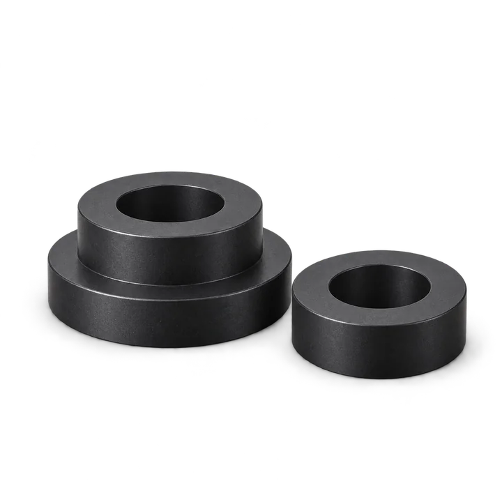
AI-generated short bonded-magnet ring geometry concept
Short rings
AI-generated bonded-magnet sleeve geometry concept
Long sleeves
AI-generated stepped bonded-magnet ring geometry concept
Stepped rings
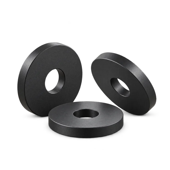
AI-generated annular bonded-magnet disc geometry concept
Annular discs
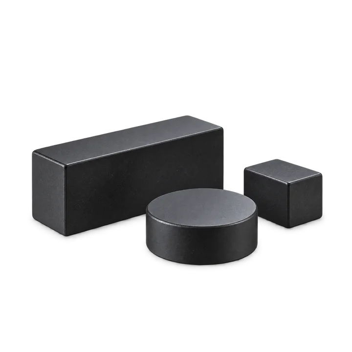
AI-generated bonded-magnet block and disc geometry concept
Blocks & discs
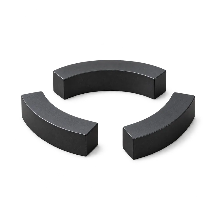
AI-generated bonded-magnet arc-segment geometry concept
Arc segments

Technical reference

Bonded magnet design details

These topics collect the useful design questions from the previous page. Numerical grade limits need the proposed material’s documentation rather than an unverified general table.

What makes a magnet polymer-bonded?

Magnetic particles are held in a binder matrix and formed into a part. Bonded NdFeB refers to the magnetic powder family; it does not identify one universal polymer, process or finished-part specification.

Polymer bonding is different from gluing an already formed magnet to a component. If the inquiry concerns an adhesive joint, identify both substrates, surface condition, loads and environment.

How do powder and binder choices affect the design?

Bonded compounds may use NdFeB, ferrite or SmCo powder. The compound’s magnetic and physical properties depend on both constituents and their proportions. A binder choice also needs a review of temperature, moisture, chemicals and assembly requirements.

Use the proposed compound’s datasheet for numerical limits. Do not transfer the performance of a sintered magnet or a powder alone to the finished bonded composite.

Are all bonded grades isotropic?

Isotropic and anisotropic materials have different orientation requirements. Confirm the proposed material and how its orientation relates to the magnetization pattern and forming process.

State whether a grade is mandatory or whether alternatives can be reviewed. A family label alone does not determine the possible pole arrangement.

What should a multipole ring drawing show?

Mark the pole count, active inner or outer surface, pole sequence, angular reference and any relationship to a key or locating feature. Include the sensor position or working gap where relevant.

Specify how pole polarity, field amplitude and any waveform requirement will be checked. Confirm the magnetization fixture and the acceptance method for the proposed dimensions.

Magnetization direction reference →
What limits working temperature?

Temperature suitability depends on the magnetic material, binder and assembly conditions. Review continuous operation, peaks and cycling with the proposed compound’s data.

Include opposing fields and the working point in the magnetic review. Also review changes in fit, environmental exposure and the other assembly materials. A generic maximum temperature is not a guaranteed finished-part limit.

What dimensions and environmental conditions need testing?

Identify critical dimensions and define the conditions under which they are measured. Discuss shrinkage, conditioning and the intended operating environment with the proposed material and process.

Specify moisture, chemical contact, handling wear and any protective finish or housing. A polymer binder does not establish waterproofing or universal corrosion resistance.

How should bonded and sintered NdFeB be compared?

Compare the complete part in its magnetic circuit: required output, available space, pole pattern, geometry, temperature, assembly steps and quantity. Neither route is automatically the best choice for every design.

A sintered material’s published magnetic values cannot be used as a bonded-part specification. Review the proposed grade and compound separately, then agree the finished-part acceptance test.

Review custom sintered NdFeB requirements →
Which inspection records should be agreed?

Agree the drawing revision, dimensional checks, pole pattern, surface condition and magnetic test arrangement. Identify the sample size and which records are needed for material properties and finished-part acceptance.

For a motor, sensor, medical device or other regulated or safety-critical assembly, provide the applicable system requirements. A generic application example does not establish device qualification.

First article inspection checklist →

From drawing to quotation

Confirm the specification before committing to tooling

  1. Step 1

    Send the drawing

    Describe the magnetic function, interfaces, working conditions and estimated quantity.

  2. Step 2

    Review the route

    Discuss powder, binder, forming method, geometry, pole pattern and any tooling needs.

  3. Step 3

    Agree acceptance

    Confirm the drawing revision, checks, samples and records required for the part.

  4. Step 4

    Confirm the quote

    Review available specifications, tooling terms, quantities, price and delivery before ordering.

Send your bonded magnet requirement

Existing video reference

Magnetization equipment video

The existing Magnetstek magnetization equipment video is retained as process context. Its contents do not replace the drawing, material datasheet or inspection requirements agreed for your part.

Watch the magnetization equipment video on YouTube →

Documents & related options

Bring the supporting information into the review

List any required compound datasheet, temperature-dependent magnetic curves, environmental test or inspection record in the inquiry. Confirm which records apply to the proposed material and can be supplied with the order.

Drawing checklist

Prepare the geometry, magnetic function and acceptance conditions.

RFQ guide →

Injection molding

Review molded geometry, inserts and material requirements.

Molded magnets →

Technical context: Arnold’s permanent magnet material and binder/process reference, Arnold’s injection-molded material explanation and Magnequench’s bonded powder explanation. These explain material and process principles; their product specifications and capabilities are not Magnetstek supply claims.