An electromagnet uses electric current in a coil to produce a magnetic field. A ferromagnetic core can concentrate that field. The useful question for an engineer is not simply whether the device is “strong,” but what force it delivers at the actual working gap, for how long, and under what electrical and thermal conditions.
How an electromagnet works
Current flowing through a wound coil creates a magnetic field. In a conventional iron-core design, the core and surrounding steel guide magnetic flux toward an armature or workpiece. Switching off the current removes the coil-generated field, although some residual magnetism can remain. Reversing current reverses the field polarity; it does not automatically make a plain iron armature repel.
Force depends on the complete magnetic circuit: coil, core, mating material, geometry and air gap. Core saturation, leakage and temperature also matter. A current rating alone cannot establish the force available in an assembly.
Holding magnet, solenoid or voice coil motor?
- Holding electromagnet: intended to retain a suitable ferromagnetic workpiece. Rated holding force is commonly specified under close-contact test conditions; any paint, coating, roughness or gap can reduce it.
- Solenoid: moves an armature over a defined stroke. Ask for force at the required stroke, not only at the end of travel.
- Voice coil motor: uses a current-carrying coil and a permanent-magnet field for controlled linear or rotary motion. It needs appropriate guidance and, where position matters, feedback. See our VCM design guide.
- Permanent magnet: provides a field without continuous coil power. It may suit an assembly where an always-on field is acceptable.
Why the working gap changes the answer
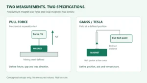
A quoted maximum pull or holding force may be measured with a flat steel armature in nearly full contact. In a real fixture, a nonmagnetic cover, adhesive, coating or mechanical clearance creates an air gap. For moving armatures, the gap changes throughout the stroke. Ask for a force-versus-gap or force-versus-stroke curve at your operating voltage and duty cycle. State the workpiece material, thickness and contact area as well.
A thin or unsuitable mating part may saturate or fail to complete the intended magnetic path. If loss of power would release a load, treat retention and fail-safe behavior as system design requirements rather than assuming the magnet will hold after power is removed.
Voltage, duty cycle and coil temperature
A coil converts electrical energy into heat. Voltage, coil resistance, current, energized time, ambient temperature and cooling path all affect temperature rise. A unit rated for intermittent operation may overheat if held on continuously. Conversely, a continuous-duty design may have different force and package tradeoffs. Specify the supply range, on/off cycle and maximum energized time before comparing products.
Coil resistance and current change with temperature, so verify performance under the expected operating conditions. A controller or driver also needs to manage switching transients; the appropriate suppression method depends on the circuit and desired release speed.
What to send with an electromagnet RFQ
A usable request describes the application rather than a single pull-force number. Include:
- Device type and task: hold, lift, latch or move; whether release on power loss is acceptable.
- Required force at the actual gap or at several points in the stroke, with the load direction and any safety factor used by your design team.
- Available envelope, mounting features, armature or workpiece material, thickness, coating and contact area.
- Supply voltage range, driver constraints, switching rate, duty cycle, maximum on-time and ambient temperature.
- Operating environment, required documentation, target quantity and drawings or sketches.
If the assembly also needs a permanent magnet, identify its material preference, size, coating, magnetization direction and operating temperature. Our custom neodymium magnet page explains those inputs. Send your drawing and operating conditions through the Magnetstek inquiry form for a scope review.
Common questions
Does reversing the wires reverse the pull force? It reverses coil polarity. A typical soft-iron armature is attracted toward either pole, so reversing current alone does not turn that setup into a push actuator.
Can a catalogue holding-force figure be used for a 2 mm gap? Not without a force-versus-gap curve or a test for that geometry. The catalogue figure may reflect direct contact with a specified steel plate.
Will the electromagnet hold a load with the power off? A standard coil-driven holding magnet should not be assumed to do so. Some designs combine permanent magnets and coils, but their power-off behavior must be specified and verified for the exact unit.
Technical references
For application-specific force and duty guidance, consult the manufacturer information from Magnet-Schultz on holding magnets and Takaha Kiko on solenoid selection. Their ratings apply to their respective devices and test conditions.