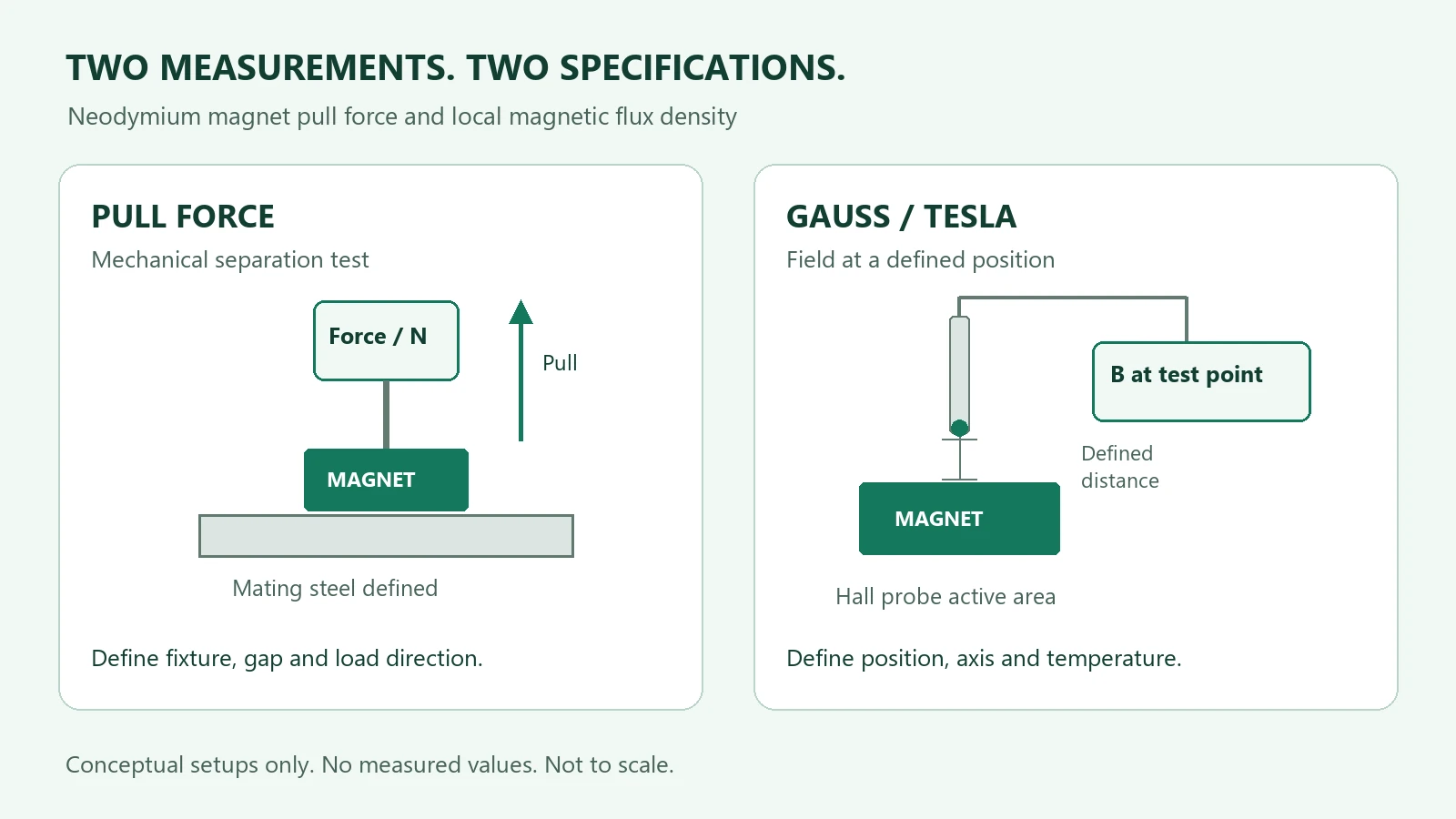
Neodymium magnet pull force and gauss describe different measurements. Pull force is the force needed to separate a magnet from a specified mating part under defined test conditions. A gauss reading describes magnetic flux density at the probe’s position. For a custom neodymium magnet, choose the acceptance test that matches the part’s job: retaining a component, providing a field at a sensor, or both.
Pull force vs gauss: a quick comparison
| Question | Pull force | Gauss or tesla reading |
|---|---|---|
| What is measured? | Mechanical separation force, commonly reported in newtons (N). | Local magnetic flux density, B, reported in G, mT or T. |
| What defines the result? | The mating material, contact geometry, gap, fixture and direction of separation. | The measurement point, probe orientation, active sensing area and surrounding magnetic circuit. |
| Which requirement does it help check? | A defined retention or release-force requirement. | A field requirement at a sensor or another specified position. |
| What should the drawing or test sheet state? | The assembled test arrangement and the permitted force range. | The coordinates, measurement axis, distance and permitted field range. |
A field value can describe one point around a magnet while leaving its behavior over a larger area or distance unspecified. K&J’s Surface Fields 101 explains why surface field alone is an incomplete description of a magnet’s three-dimensional field.
Can you convert gauss directly into pull force?
A single gauss reading does not provide a general conversion to newtons or holding weight. Estimating force requires a model of the geometry and magnetic circuit. A point reading does not describe the field across the entire interacting area.
K&J notes that simplified force calculations based on flux density can disagree with real measurements. Its magnet calculator guidance also identifies assumptions about geometry and magnetization. Use a calculation for its stated setup, then validate the relevant arrangement rather than converting a catalog gauss value into a load rating.
Why a catalog pull-force value may differ from your assembly
A normal pull-off test measures separation away from the mating surface. The result depends on how that surface and the magnet are presented to each other. K&J’s pull-force testing explanation describes controlled steel, contact and fixture conditions used for its own measurements.
- Mating steel: identify its material, thickness and contact area.
- Separation: include air gaps, paint, coatings, spacers and imperfect contact.
- Assembly: show any cup, backing steel, housing and nearby magnetic parts.
- Load direction: distinguish straight pull-off from sliding, peeling or an off-center load.
A magnet resisting a sliding load on a vertical steel panel involves friction as well as magnetic attraction. A direct pull-off result therefore should not be relabeled as the permitted sliding load. K&J’s practical holding-force discussion describes this distinction. Define and test the intended load case; these examples do not establish a safe working load for lifting equipment.
Why two gaussmeter readings may differ
A repeatable field measurement needs a repeatable probe position and orientation. The sensing element can be inside the probe rather than at its visible tip. Lake Shore’s Hall probe selection guide explains how active area, field gradients and the distance from the sensing element to a magnet affect the reading.
For acceptance, mark the measurement point relative to a mechanical datum, specify the field component or probe orientation, and state the temperature and assembled configuration. If a sensor operates across a working gap, measure or specify the field at that location instead of substituting a surface reading. The sensor magnet working-gap guide develops that application-specific check.
Two ways to write a reviewable requirement
The following wording is a specification template, not a test result or an offer of a particular tolerance. Replace the bracketed items with the equipment designer’s requirements.
For a magnetic closure
“Evaluate the magnet in drawing [revision] against mating steel [material, dimensions and finish], with [gap or spacer]. Pull in direction [axis] using fixture [reference]. Required separation force: [range and units] at [temperature]. Confirm the test method and records with the quotation.”
For a position sensor
“Provide magnetic flux density [range and units] at point [coordinates] relative to datum [reference], at working gap [distance]. Measure component [axis] with probe [type or agreed method], in assembly [reference] at [temperature]. Confirm polarity and the acceptance record.”
If the same part has both retention and sensing duties, list both checks. Agree how samples will be evaluated before treating either measurement as sufficient for the finished assembly.
What to send with a custom NdFeB magnet inquiry
- A dimensioned drawing with revision, finished geometry and critical tolerances.
- The requested material or grade, coating and magnetization direction, if already fixed.
- The mating parts, working gap and service environment.
- A force requirement, a field requirement, or both, with the measurement conditions.
- The sample and production quantities, acceptance limits and required inspection records.
Use the drawing and RFQ checklist to prepare the geometry, and the first article inspection checklist to identify the records needed for sample approval.
Magnetstek reviews these inputs for a part-specific quotation. Confirm which material data and inspection documents apply to the proposed part and can be supplied with the order. Reference data from another manufacturer does not define a Magnetstek product.
Review custom neodymium magnet options →
Technical sources
- K&J Magnetics: Surface Fields 101, local field values and geometry.
- K&J Magnetics: Magnet Pull Force Calculator, model assumptions and validation limits.
- K&J Magnetics: Testing Magnet Strength, pull-test conditions.
- K&J Magnetics: How Much Will a Magnet Hold?, load direction and friction.
- Lake Shore Cryotronics: Hall Probe Selection Guide, sensing area, position and orientation.