- Custom Magnets
- Standard Magnets
- Mounting Magnets
- Magnetic Assemblies
- About Us
- Knowledge


Menu
Custom NdFeB parts · Drawing review
Specify the magnet for your assembly
Send your drawing for a review of a custom neodymium-iron-boron (NdFeB) magnet. Define the finished geometry, pole direction and field or force you need in the assembly. Magnetstek reviews the proposed grade, coating and inspection requirements before confirming feasibility and a quotation.
Minimum order quantity, available specifications and lead time are confirmed for the individual part. Include any dimensions or test conditions that are still open for discussion.
Start with a geometry
Choose a starting shape, then specify the finished dimensions, pole direction and operating conditions.
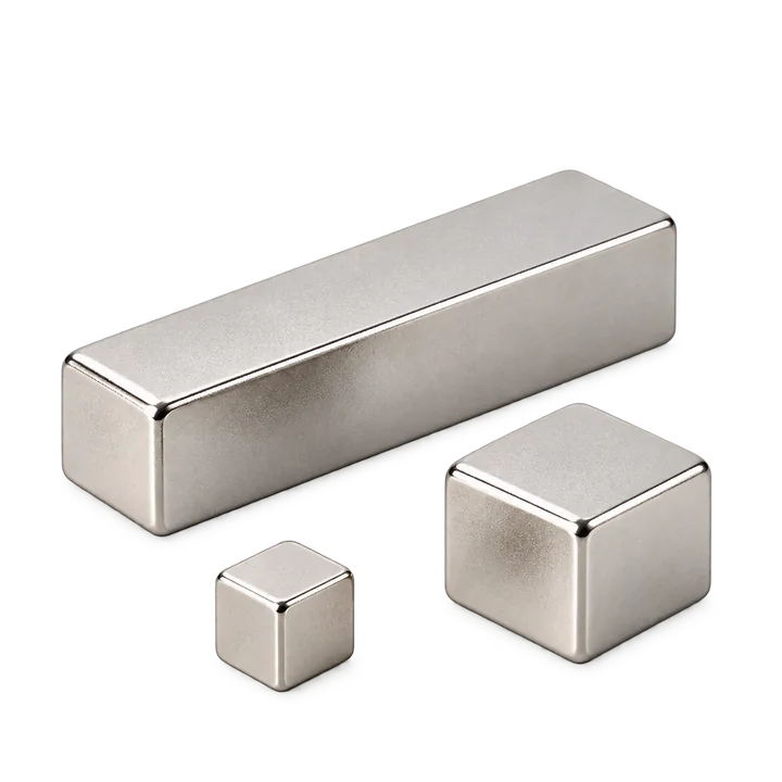
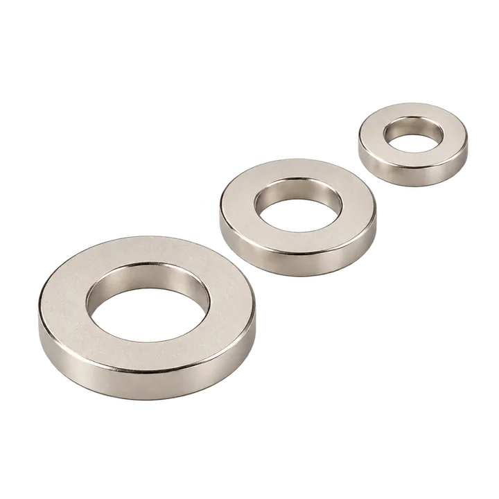
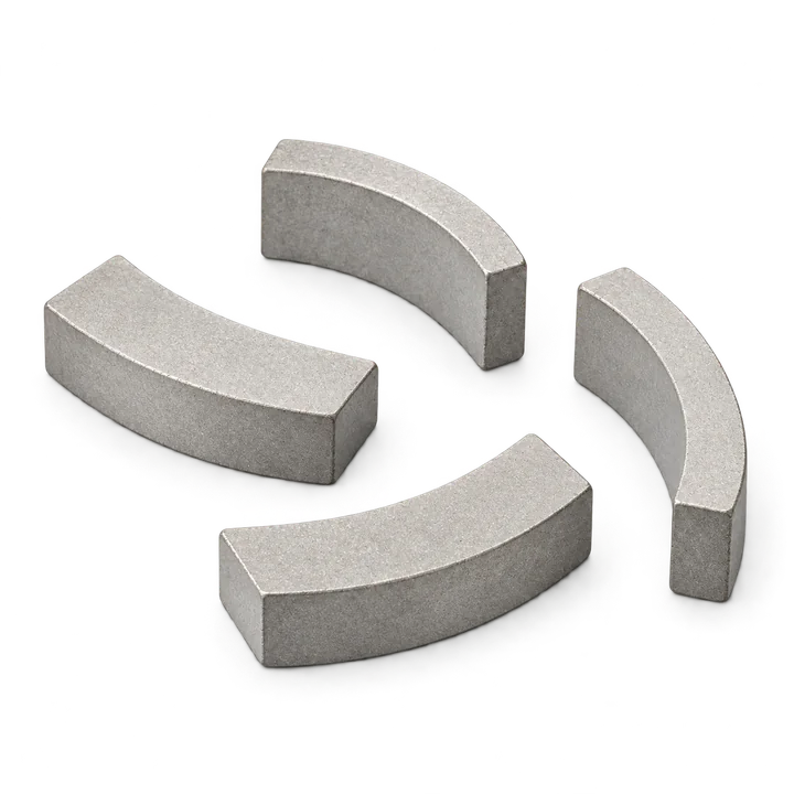

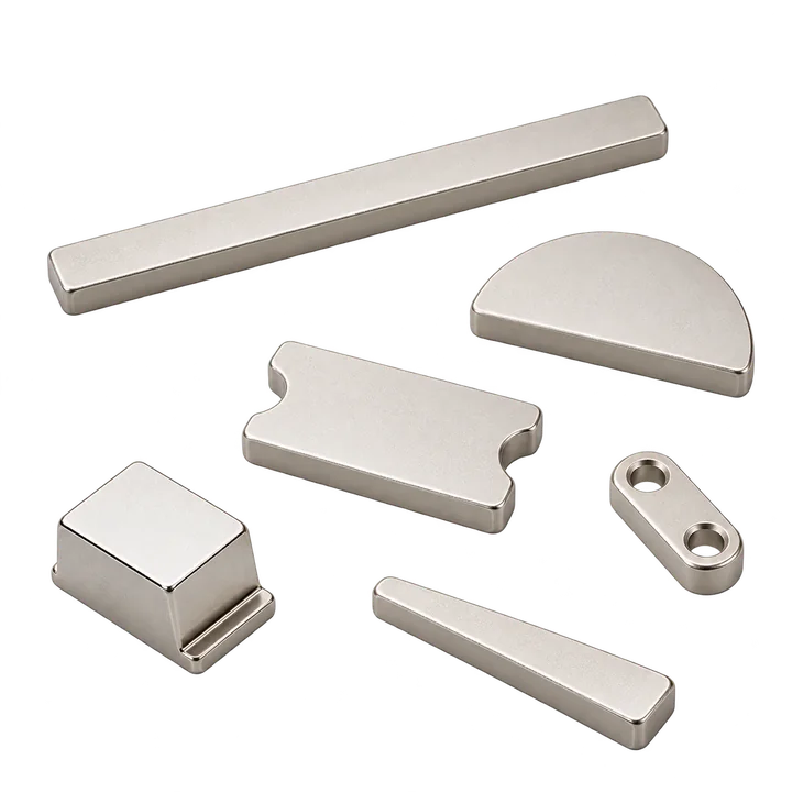
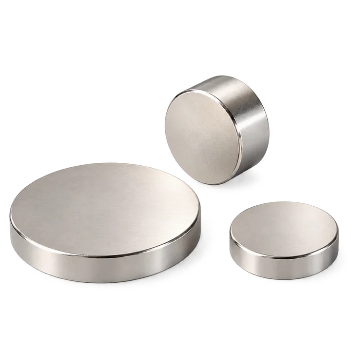
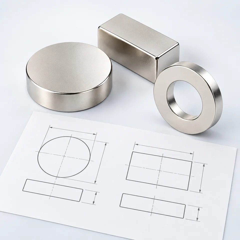
Illustrative product shapes. Final geometry, finish and pole direction are confirmed from your drawing.
A clear starting specification
Show dimensions, holes, edge details and the tolerances that affect fit. Identify the drawing revision.
State the field or force, measurement position, working gap and acceptance range. Include the test setup.
Give a preferred grade if known, plus normal and peak temperatures, exposure duration and opposing fields.
Describe moisture, chemicals, cleaning and wear. Include the finish, dimensional allowance and coating test requirements.
Mark the pole faces or axis. Show the pole pattern when the design needs multiple poles.
State sample and production quantities, the required inspection records and any requested delivery date for review.
Product photographs
These product photographs show discs, rings, blocks and shaped segments supplied as examples by Magnetstek. Use the geometry as a starting point, then define the finished dimensions, coating and pole direction for your application.
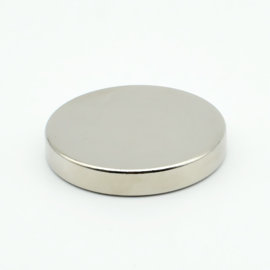
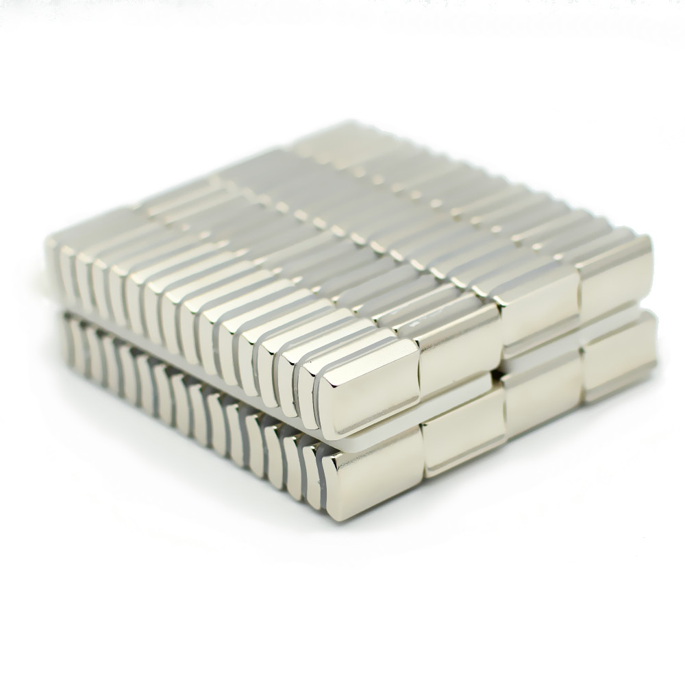
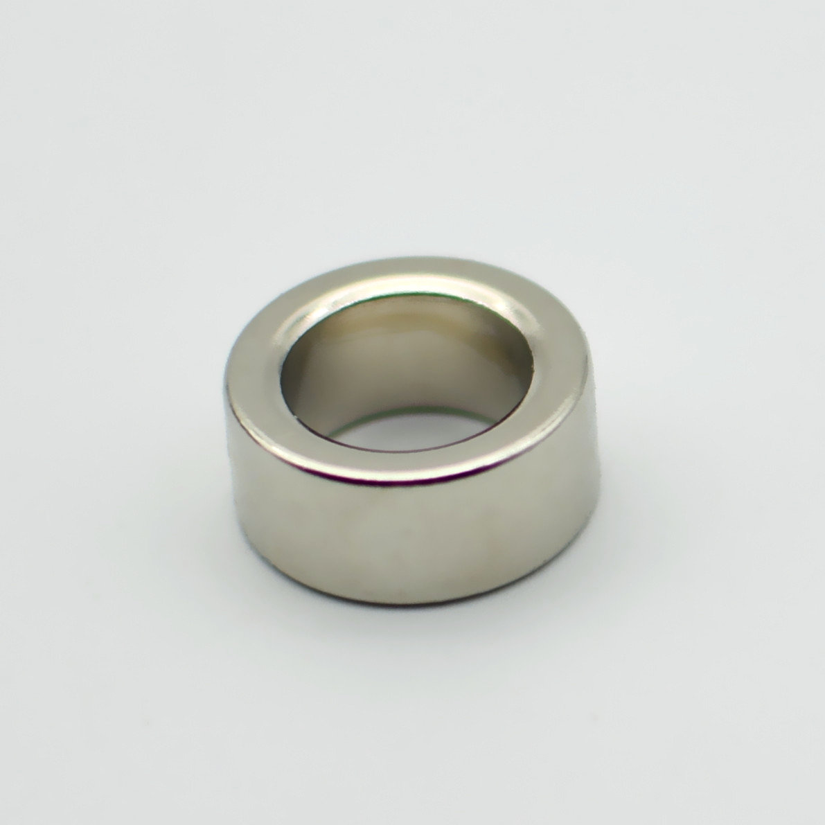
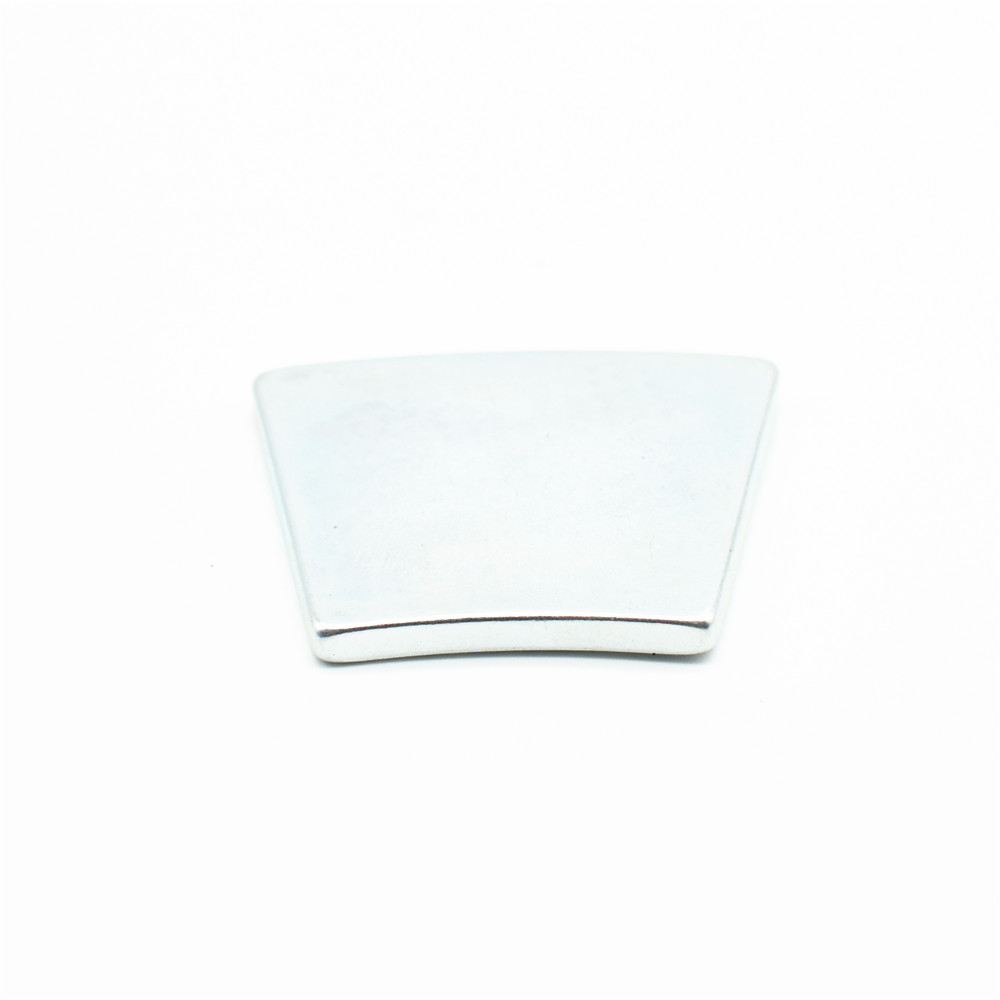
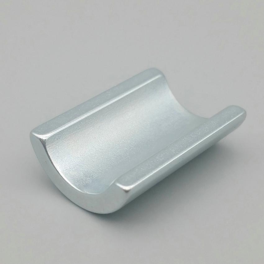
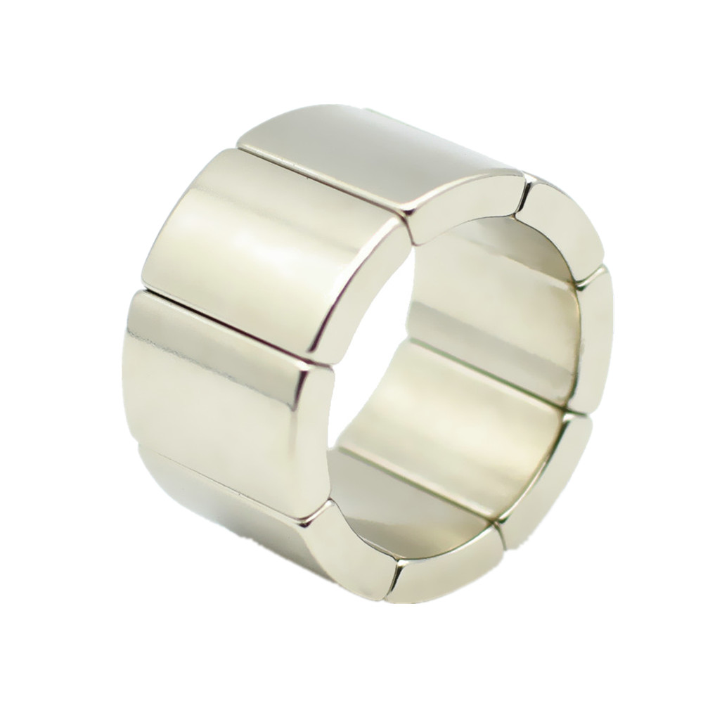
The segmented ring shown here is assembled from separate arc pieces. A photograph does not establish the material grade, magnetization pattern or current availability.
From material to finished part
A magnet grade describes material properties. The field and force in an assembly also depend on the magnet's dimensions, pole direction, working gap and nearby magnetic parts. A higher grade number alone cannot establish the holding force or sensor signal that the finished device will produce.
For a holding application, describe the mating steel, contact condition, pull direction and measurement method. For a sensor, specify the field at the sensing position and the gap over which it must work. A drawing of the surrounding assembly helps connect the material choice to a result that can be checked.
Sintered NdFeB is based on neodymium, iron and boron. Compare the proposed grade's remanence, intrinsic coercivity, energy product and demagnetization curves with the design requirements. Read the grade designation together with the producer's data and the conditions attached to it.
Use the NdFeB grade guide to prepare candidate questions. Confirm the actual grade, specification revision and applicable values during the quotation review. General material references help explain a grade; the agreed specification defines the requirements for the order.
Discs, blocks, rings and arcs are useful starting shapes. The drawing should also show features such as holes, chamfers, thin sections and the surfaces that locate the part in its assembly. Identify which dimensions are critical and whether they apply after coating.
Sintered NdFeB is brittle. Review edge details and the assembly method before treating the geometry as final. Requested tolerances, size and magnetization feasibility need a review for the particular design. Use the drawing and RFQ checklist to describe the finished part and separate confirmed requirements from dimensions that can be discussed.
Discuss nickel-copper-nickel, zinc, epoxy or another required finish in the context of the assembly. Describe humidity, contact with liquids or chemicals, cleaning, handling wear and any housing or encapsulation. Include the coating allowance where it affects the finished dimensions.
Agree the coating system and any inspection or exposure test with its method and acceptance criterion. A salt spray duration alone does not establish service life in the application. The coating specification guide explains the information to include in a review; a coating test result needs the conditions and specimen details that make it meaningful.
Identify the required pole faces, magnetization axis or pole pattern. For a ring or arc, show where the working field is needed and how the part sits in the magnetic circuit. A shape name by itself leaves the pole arrangement open.
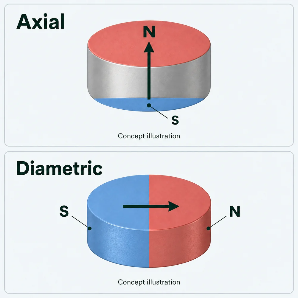
Include the polarity or field check that will be used for acceptance. Axial, diametric and multipole designs have different geometry and fixture requirements, so the direction should be reviewed with the finished dimensions before quotation.
State continuous and peak temperatures, exposure duration, thermal cycling and any opposing magnetic field. Review the proposed grade's data and demagnetization curves for the finished geometry and working point. A published temperature rating needs those conditions before it can guide a part specification.
Include the coating, adhesive, housing and other assembly materials in the temperature review. If another material is being considered, compare SmCo and NdFeB using the requirements of the same assembly. Confirm the proposed material and its acceptance conditions before placing an order.
Curie temperature is different from the allowable operating temperature; irreversible magnetic losses can occur below the Curie point. K&J's temperature guide explains the distinction.
Read the temperature review notes ↓Application inputs
Application details help define the drawing review. Include the surrounding components and the output that will be measured in the device.
Provide the magnet layout, pole arrangement, mating parts and operating conditions, including temperature and any opposing field.
Identify the sensing position, working gap, required polarity and field range across the intended movement.
Describe the magnetic circuit, available space and the field or force requirement at the working position.
Show the mating surface, contact area, gap and load direction. Specify the test setup for any required holding force.
Define a sensor magnet working gap · Review magnet rotor requirements
From sample review to delivery
Define what will be measured and which documents are needed before confirming the order.
Set acceptance criteria for the finished dimensions, coating condition, polarity and magnetic output. A field or force requirement should identify the fixture, measurement location, working gap, temperature and allowed range. Use the same conditions when comparing samples and later deliveries.
Identify the requested sample size, records and any first article checks before quotation. A material property and a measurement in the assembled device answer different questions; the inspection plan should state which evidence is required for each. Use the first article inspection checklist to prepare a review sequence.
If your review needs a material datasheet, temperature-dependent demagnetization curves, a coating report or an inspection record, list the required documents in the inquiry. Confirm which records apply to the proposed material and which can be provided for the order. Reference data from another producer does not establish the specification of a Magnetstek part.
Arnold's NdFeB material reference explains grade-specific data. ASTM B117 describes a salt spray test practice and the limits of interpreting its results. Use those sources for technical context alongside the agreed drawing and material documentation.
Recorded dimensional example
A Magnetstek inspection record dated 28 August 2026 lists 25 samples for a ring with nominal outer diameter 7.60 mm, inner diameter 4.30 mm and height 11.50 mm. The record identifies the grade as N48 and the finish as NiCuNi.
The recorded dimensional ranges are:
This is a separate inspection example from the product photographs above. Its dimensions and tolerances apply to that record; agree the requirements and inspection scope for your part in the quotation. Dimensional results do not establish magnetic output or coating service life.
Prepare dimensions, operating conditions and acceptance criteria.
Read the guideUnderstand material properties and grade selection inputs.
Read the guideDefine the finish, environment and inspection requirements.
Read the guidePlan how the finished part and assembly will be checked.
Read the guideMaterial selection: SmCo and NdFeB comparison · Custom SmCo magnets · Certificate scope
Protect brittle magnets from impacts and from snapping together during handling. Review spacers, packaging and the assembly method for the part's size and shape. Identify any edge or surface damage that would fail inspection. Keep storage conditions consistent with the agreed coating and packaging requirements, and include handling requirements in the RFQ.
Strong magnet safety: Keep magnets out of reach of children. Strong magnetic fields can interfere with implanted medical devices; follow the device manufacturer's guidance. See CPSC magnet safety and FDA guidance on magnetic interference.
Technical reference
Explore the material and design principles behind the drawing review. These notes explain what to compare; the agreed material data, finished-part drawing and acceptance plan define the order.
Sintered neodymium magnets are hard permanent magnets based on neodymium, iron and boron. The material is brittle, so a finished magnet needs to be treated differently from a ductile steel part. The geometry, material orientation, coating and pole direction belong in the same design review.
A grade designation summarizes material properties; it is not a direct rating of the finished assembly's pull force. Read the proposed specification revision and the conditions attached to each value.
Technical context: Arnold's NdFeB material reference. Its published grades and values describe Arnold materials, not a Magnetstek delivery specification. Arnold also explains the hysteresis-loop parameters (PDF).
The operating point is set by the magnet and the rest of its magnetic circuit. Changing the magnet's proportions, opening a working gap, adding a steel return path or applying an opposing field can change that operating point. This is why two parts of the same grade can behave differently.
Pull-off force also depends on the mating steel, its thickness and contact area, surface coatings, gap and direction of loading. A direct pull test against steel does not describe resistance to sliding or performance across a different gap. For a sensor, the useful quantity may instead be field strength and polarity at the sensing position.
Compare candidate parts using the same geometry, temperature and measurement setup. Document the target field or force, where it is measured and the allowed range. A material datasheet and an assembly test answer different questions.
Magnetic properties change with temperature. A reversible temperature coefficient describes a change over a stated temperature range that can recover when the magnet returns to the reference temperature. It is not a complete prediction of output across every temperature or magnetic circuit.
Irreversible demagnetization can leave a magnet weaker after it cools. The risk depends on the grade's temperature-dependent curves, the part's geometry and working point, and any opposing field. A catalogue operating-temperature value therefore needs to be read with its conditions. Exposure time and thermal cycling should also be included in the application review.
Curie temperature is the material's magnetic transition temperature; it is not a recommended operating limit. An NdFeB part can suffer irreversible loss below that point. The coating, adhesive, housing and other components may impose additional temperature limits.
Technical context: K&J's explanation of temperature, working point and magnetic loss. Request applicable curves for the proposed material rather than copying a generic maximum temperature.
A magnet drawing should distinguish the finished dimensions from any dimensions before coating. Identify locating surfaces, critical fits, holes, slots, chamfers and edge requirements. A single overall tolerance can leave the dimensions that control assembly performance unclear.
Thin sections, sharp corners and narrow material around holes need particular attention because sintered NdFeB is brittle. Do not assume that holes or edge features can be added to a coated, magnetized part without affecting the part. Review those features before the finished geometry and inspection method are agreed.
Use a drawing revision and identify dimensions that are essential versus those open to discussion. Refer to the drawing and RFQ checklist for the information needed to review a custom shape.
NdFeB can corrode when exposed to moisture or an unsuitable environment. A coating is part of the protection system, together with the part geometry, handling and any housing or encapsulation. Surface damage, exposed edges and the actual service exposure matter when comparing finishes.
Specify the required coating system, coverage and thickness where it affects fit. Describe moisture, chemicals, cleaning, wear and contact with other materials. Nickel-copper-nickel, zinc and epoxy are finish options to discuss against those conditions; naming a finish alone does not establish suitability for an application.
A corrosion-test duration needs its test method, specimen condition and pass/fail criterion. A salt spray result cannot by itself be converted into years of service life. The coating specification guide and ASTM B117 test practice provide context for defining the test.
For a disc or ring, axial magnetization places the opposing poles on the two flat faces. Diametric magnetization runs across the diameter, with opposing pole regions on opposite sides. A radially magnetized ring is a different arrangement, with an inner-to-outer direction; the terms are not interchangeable.
For a block or an arc, mark the required pole faces or axis on the drawing. An arc shape does not establish a radial magnetization pattern. Multipole designs additionally need a pole layout, pole count, orientation and a method for checking the pattern.
The drawing should also identify how the part sits in its assembly and where the working field is needed. Review the pole arrangement together with the dimensions and material before treating the magnetization as final. See the magnetization direction reference for illustrated examples.
Application names identify a starting point, rather than a qualification of a particular magnet. The useful specification describes the magnetic circuit and the output that must be produced in the device.
For a safety-critical or regulated device, the component and assembled system need the applicable qualification and acceptance work. A general application description does not establish certification or suitability.
Material-property records, dimensional checks and magnetic-output tests provide different evidence. Agree which records apply to the proposed grade, which identify the delivered part, and how the finished geometry, coating and pole orientation will be checked.
A reproducible magnetic test states the fixture, position or working gap, temperature, direction and acceptance range. Establish the sample or first-article checks before comparing later deliveries. Use the first article inspection checklist to structure that review.
Packaging and handling also affect the accepted part. Keep magnets separated and protected against impacts and snapping together. Agree what edge damage or coating damage is unacceptable and how parts will be identified and packed. Store them in conditions consistent with the coating and packaging specification.
From inquiry to order
Step 1
Include a drawing or dimensioned sketch, the application and quantities. Identify unknown grades or design details so they can be discussed.
Step 2
Review material, geometry, coating, pole direction and inspection requirements together. Identify the drawing revision and documents required with the order.
Step 3
Check the quoted specification, quantity, price, minimum order quantity, lead time and documentation scope before accepting. State sample and production quantities separately.
Step 4
After the quotation is agreed, confirm order details and payment instructions with Magnetstek. Agree any sample approval or first-article checks before the relevant production release.
Submitting the inquiry form requests a quotation. It does not place an order or collect payment. Read the custom magnet ordering process for the next steps.
Practical quote questions
These notes focus on sintered NdFeB. For polymer-bonded magnets, including injection-molded designs, start with the bonded magnet and injection-molded magnet pages. Review the material specification, geometry and manufacturing route together for the proposed part.
An existing size may be worth reviewing before specifying a new geometry. Check the standard magnet size reference against the required grade, coating, pole direction and finished dimensions. Availability, price and delivery need confirmation for the request.
Yes. Send the finished geometry, application and target field or force with the operating conditions. Mark any unknown values. The drawing review can then address the material choice and the information needed to confirm it. A preferred grade is useful when it is already part of an approved specification.
State the mating material and its thickness, contact area, working gap, pull direction and test method. Give an acceptance range and describe the fixture. These details allow the requirement to be assessed for the actual installation and reproduced during inspection.
Send the drawing with the critical dimensions and requested tolerances, including any coating allowance. Size, thin sections, edge features and pole direction need to be reviewed together. Feasibility and the inspection method are confirmed for the design before those requirements become part of a quotation.
State the records you need when requesting the quote. The proposed material, inspection plan and documentation scope must be agreed for the order. A general grade table, product photograph or reference coating test does not establish which reports accompany a particular delivery.
They are confirmed in the quotation for the reviewed part. Include the sample quantity, expected production quantity, drawing revision and requested delivery date. Material, geometry, finish, magnetization and inspection requirements need to be settled before the commercial details can be confirmed.
Product and process videos
Attach a finished-part drawing or dimensioned sketch and describe the magnet's role in the assembly. Include the required field or force, pole direction, operating conditions, quantity and inspection criteria. Identify any documents or details that still need discussion. Magnetstek can review feasibility and confirm the specification, minimum order and lead time in a quotation.
Request a drawing review